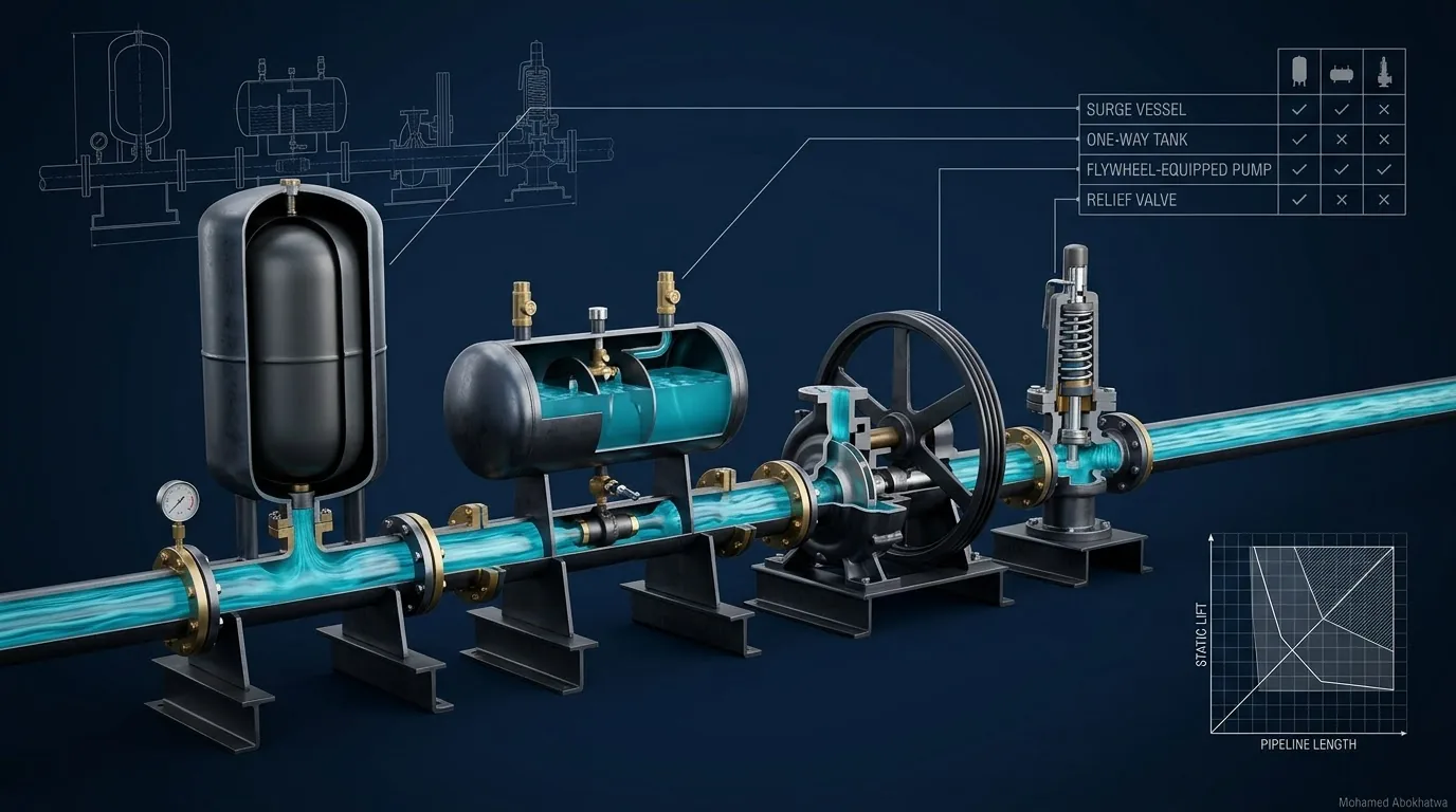
Stop the pumps instantly on a 12 km DN800 transmission main with no protection and the whole line reaches vapour; when the cavities collapse the head reaches 165–190 m against a 136 m pipe class. Three remedies were modelled on the same pipe. A 20 m³ surge vessel holds it between +4.3 m and 119.2 m; a 400 kg·m² flywheel at +9.3 m with nothing above the steady 85.0 m, if the motor can start it. A relief valve set at 95 m holds the pump end at about 96 m but leaves the line at vapour and a maximum of 127–143 m, either side of the limit depending on the cavity model. The fourth device, a one-way tank, earns its place only where the profile has a knee. There is no best surge device — only the right one for a line, a load case and a site.
1 · Start from the load case, not the device
Vessel or relief valve? is the wrong first question. A surge device protects one side of the pressure wave, at one place, against one family of events, so the design starts with the load cases. In our practice, for a pumped transmission main they are:
- Power failure at the highest flow, all duty pumps tripping at once with nothing controlling the rundown. On most pumped mains this case sizes the protection, and it is the case used here.
- A single pump trip and pump starts, including a restart while the column is still moving.
- Valve closures — see control valve water hammer and control valve transients in HAMMER — and check valve closure against reverse flow (check valves and water hammer).
Each case produces an envelope: the highest and lowest head reached at every point on the line. The limits are fixed before any device is chosen — here +3.0 m everywhere and the 136 m allowable of the PN16 class, within the design-pressure framework of EN 805 [11]. Surge scenarios in pumping stations shows why the power failure usually governs, and the classical texts treat the pump trip as the defining transient of a pumping main [1][3].
2 · The reference pipeline, unprotected
The series uses one pipeline so that devices compare on equal terms: 12 km of DN800 ductile iron K9 to ISO 2531 [12], laid flat, carrying 2,520 m³/h (0.70 m³/s, 1.39 m/s). With a wave speed of 1,050 m/s the pipe period 2L/a is 22.9 s and the Joukowsky head is 149.1 m. The steady grade line is 85.0 m at the pump and 44.8 m at the delivery reservoir; any vessel gas follows a polytropic exponent of 1.2.
The unprotected run stops the pump instantly and shuts its check valve at once — the bounding case of a set with very little inertia. The head at the pump tries to fall by 149.1 m, but only 94.8 m separate the steady head from vapour. The column separates at the pump and the low-pressure wave runs the full length: the whole 12 km reaches vapour. When the reflection returns and the cavities close, the head is thrown to 165–190 m, above 136 m over 12.0 km of line in one cavity model and 11.0 km in the other.
A real set runs down for a moment first. In the simplified rundown model of the flywheel article, with 25 kg·m² assumed for this 685 kW set, the pump end holds +2.5 m but the line still reaches vapour from about 7.4 to 11.3 km; no maximum is quoted, because that run was not repeated with the gas cavity model. That model lets a slowing pump pass some water from its suction, so it does not shrink exactly to the instant stop. Either way the bare line fails.
How these numbers were produced
Every transient figure in the series comes from a method-of-characteristics model with a vapour cavity model, cross-checked with a gas cavity model and an independent second code, on 120 reaches over 150 s [1][2]. The pump boundary differs by option: the unprotected, vessel and relief-valve runs stop the pump instantly behind an ideal check valve; the flywheel runs model the rundown, because the inertia is the device. Results without cavitation are quoted to 0.1 m. A maximum that follows a cavity collapse is quoted as a range across the two cavity models: the spike depends on how the cavity is represented, both textbook models are legitimate [9], and on the collapse peaks of this series the gas cavity model puts them between 18 % lower and 10 % higher than the vapour cavity model. These are not Bentley HAMMER results. They are a consistent basis for comparing devices; a project must still be analysed on its own profile in HAMMER or an equivalent tool.
3 · Three devices, one pipeline
Three devices were modelled for the same power failure, each sized or set the way a designer would specify it; the detailed articles of the series carry the derivations.
| Option | Line min. | Line max. | +3.0 m / 136 m |
|---|---|---|---|
| No protection | −9.8 m | 165–190 m | Fails both |
| Air-over-water vessel: 20 m³ shell, 3.5 m³ gas, differential DN400 | +4.3 m | 119.2 m | Passes both |
| Flywheel: 400 kg·m² total | +9.3 m | 85.0 m | Passes both |
| Relief valve: DN250, set 95 m | −9.8 m | 127–143 m | Fails +3.0 m; 136 m depends on the cavity model |
The vessel
The vessel is a source of water at the pump. Gas at 9.35 bar abs pushes water into the line the instant the pump stops, so the column slows over tens of seconds instead of one. The 3.5 m³ of gas expands to 16.17 m³, leaving 3.83 m³ of water in the shell, and the lowest head, +4.3 m, is 4.3 km out. On the return, the high-loss direction of the differential connection (loss coefficient 2 out, 10 in) trims the maximum from 127.5 m with a free connection to 119.2 m, with the minimum almost unchanged (+4.5 m free, +4.3 m differential). The bare duty with a free DN400 connection is 3.08 m³ of gas expanding to 15.30 m³ in a 19.1 m³ shell; the method is in sizing the hydropneumatic surge vessel.
The flywheel
The flywheel keeps the pump itself delivering. The set's own inertia, taken as 25 kg·m² for a 685 kW four-pole machine at 1,480 rpm, is not enough: the line still reaches vapour between about 7.4 and 11.3 km. Sixteen times that — 400 kg·m², 4.80 MJ at speed — holds +9.3 m at 3.0 km with nothing above the steady 85.0 m, because no cavity forms to collapse. Other plausible pump torque laws move the minimum between about +7 and +9 m, still a pass. The price is a start of about 28 s with half the rated 4,420 N·m available (pump inertia and the flywheel).
The relief valve
The relief valve caps the head where it stands. Modelled as an idealised spring valve with no opening delay, it keeps the pump end within about a metre of 95 m while discharging up to 0.416 m³/s, 59 % of the pumped flow — and a 95 m set is only 10 m above the steady head, so nuisance opening is a real risk. But a trip starts with low pressure, and the valve only opens on high. It cannot stop the line reaching vapour, and at this setting the collapse peaks form 11–12 km out: 127–143 m, above 136 m over 1.6 km in the vapour cavity model and nowhere in the gas cavity model. Lowering the set point from 120 to 95 m trims that far-field peak from 140–155 m to 127–143 m, but no setting tried brings it below 136 m in both cavity models, and valve size changes nothing out on the line (what a valve at the pump can protect).
4 · Interactive: four options on one pipeline
Each bar spans the lowest minimum to the highest maximum on the line. Where the maximum follows a cavity collapse, the paler cap is the spread between the two cavity models.
At the default the unprotected line spans −9.8 m to 165–190 m. The vessel and the flywheel bring the whole bar inside the band between +3.0 m and 136 m by different routes: the vessel feeds the line and absorbs the return, the flywheel never lets the column stop abruptly. The relief valve lowers the top of the bar but leaves its foot at vapour, and its cap straddles 136 m — a verdict no designer can sign.
5 · Interactive: where and when each option acts
A pass or fail hides where and when the limit is approached. Switch between the envelope along the line and the head at the pump against time — the two views you read in any transient package.
The default is the relief valve. Its maximum envelope rises away from the pump and peaks 11–12 km out, while the minimum lies on vapour for the whole 12.0 km. The vessel's minimum dips to +4.3 m at 4.3 km, the flywheel's to +9.3 m at 3.0 km. In the time view the vessel's pump-end head bottoms out at +4.9 m about 43 s after the trip, while the relief valve's sits at vapour for more than 45 s, until the columns rejoin and the valve takes the head to its set point.
6 · What each option really protects
Stripped to its physics, every device either adds water where the pressure falls, removes water where it rises, or slows the change of flow that causes both [1][2][3].
- Surge vessel — both sides. It adds and removes water at the pump; in our practice it is usually enough on its own on a flat or steadily rising line, though a knee or high point can make it very large. Its duty is robust: from 700 to 1,300 m/s the required gas moves only between 3.08 and 3.19 m³, falling to 1.99 m³ at 450 m/s and to none at 300 m/s (wave speed). The type changes the shell, not the hydraulics: a bladder vessel needs 23.2–28.4 m³ at any pre-charge from atmospheric up to 0.95 of the minimum, against 19.1 m³ air-over-water, because its gas is pre-charged below the minimum pressure (vessel types; pre-charge and gas setting). It is a pressure vessel [14], and a membrane in contact with drinking water needs potable approval [15].
- Flywheel — both sides, by prevention. Passive, present whenever the pump turns, no controls. It needs a rundown that is a real fraction of the pipe period; on long lines the inertia outgrows what a motor can start or a shaft and bearings can carry [2][3][5].
- Surge relief valve — upsurge, at the valve. It removes water above its set pressure, there and nowhere else. It is the right primary device where the upsurge comes first — a fast closure at the end of a gravity line — and a useful second device behind a vessel. Set pressure, overpressure and reseating are defined in ISO 4126-1 [13].
- Surge anticipator valve — upsurge, earlier. It opens on the initial low pressure, so it is already open when the return arrives and avoids the relief valve's lag — but it adds no water on the downsurge. It was not modelled in this series.
- One-way surge tank — downsurge, locally. It feeds the main when the head at its connection drops below the tank level [4][7]. On a rising-profile variant of the reference main, a vessel alone needed a 104.5 m³ shell; with a tank at the knee it needed 37.8 m³, 64 % smaller (one-way tanks at the knee). This flat line has no knee or high point, so a tank has nothing to do here and was not modelled on it; and alone, on the knee profile, it made the pump-end collapse worse.
- Air valves — a complement. They admit air at a high point to hold the local pressure near atmospheric; the air must then leave without a slam, and the pocket changes the next wave [8][10]. Every main needs them for filling and draining (air admission in networks); none should be the primary downsurge device without a model that includes them.
7 · Screening before modelling
Five numbers from day-one data say how hard the problem is and which devices are worth modelling. None of them is a design.
\(\Delta H\) is the head change of an abrupt stop, \(T_r\) the time for the wave to reach the far end and return, and \(2\rho^*\) Parmakian's pipeline parameter — the Joukowsky head over the absolute steady head at the pump \(H_0^*\) — used to enter the classical air-vessel charts [4][6]. On the reference line, with the nominal 0.8 m bore:
The fourth is a column-separation screen. On a flat line the first downsurge of an abrupt stop reaches vapour at the pump if
which agrees with the instant-stop model. The screen assumes the pump stops much faster than 2L/a, and it only works one way: a yes is reliable for an abrupt stop, a no proves nothing. Pump inertia softens the first wave and moves separation out along the line — with the set's own 25 kg·m² the rundown model keeps the pump end at +2.5 m while vapour forms 7.4 km out — so for a real set a yes means model it, not proof of separation at the pump. At 450 m/s the Joukowsky head is 63.9 m and the screen says no, yet the head at the pump drops to 21.1 m, keeps sinking as the wave travels out and the friction gradient that held the line up unwinds, and reaches vapour about 42 s after the trip. Only at 300 m/s does the unprotected line stay above vapour, at +5.0 m. The fifth number screens a flywheel against the pipe period [3][5]:
On this line \(\tau/T_r = 0.15\) (200 kg·m²) still failed the +3.0 m criterion and 0.31 (400 kg·m²) passed with margin — an observation on one line, not a rule. It says nothing about the start, which grows with inertia as \(t_{start} = I\,\omega_0/T_{acc}\): 1.8 s for the bare set and 28.1 s with the flywheel, at half rated torque.
8 · Interactive: screening explorer
Enter your own line. The chart plots the Joukowsky head across the range of wave speeds against the head available above vapour and above +3.0 m; the marker is your line.
The defaults reproduce the reference line: 1.39 m/s, 149.1 m, 22.9 s, 2ρ* = 1.56, and a red screen, because 149.1 m exceeds the 94.8 m above vapour. The Joukowsky line crosses the vapour line at \(a = g(h_0+9.8)/v_0\), about 670 m/s here: a ductile iron or steel main of this size is at risk of separating on its first wave if the pump stops abruptly, and a PE main may not be — which is not the same as safe. Set the inertia to 400 kg·m² and τ becomes 7.01 s, 0.31 of the period, and the screen turns amber: the rundown may prevent separation, so model it (on the reference line even 100 kg·m², 0.08 of the period, kept the rundown model just off vapour). Stretch the line to 60 km and the 400 kg·m² flywheel is 0.061 of a 114 s period — the length argument against flywheels in one number.
9 · Site and operation factors
Options that both pass are separated by what the model does not see. These are engineering judgement, not rules.
- The critical side. If the downsurge reaches vapour, only devices that add water or slow the flow change qualify; relief and anticipator valves come after the downsurge is solved.
- Profile and length. Knees and high points attract the minimum envelope and suit one-way tanks and air valves; a flat line spreads the problem and favours protection at the pump. Long lines push flywheels out of reach.
- Power and starts. A weak grid means frequent trips and restarts, and a flywheel lengthens every start: confirm starting class and starts per hour with the motor manufacturer. A variable-speed drive shapes controlled stops, but on a power failure it has no supply and the pump runs down on its own inertia.
- Operation and maintenance. Compressors and level instruments, pre-charge checks with the vessel isolated, valve function tests: choose what the operator will actually maintain (surge analysis and risk). Some failures are silent whatever the device — lost gas, a ruptured bladder, a seized relief valve — so log pressures and alarm on vessel level or pre-charge (transient analysis and SCADA).
- Footprint and relative cost. In our experience valves are the smallest items, flywheels sit between, and vessel installations with compressors and civil works are the largest. The order is site-dependent, and the cheapest device that fails a limit is not an option.
- Redundancy. With one vessel isolated for inspection, can the station still run? Split the volume or restrict pumping, and model that case.
10 · Interactive: weighted decision matrix
Once the model has removed the options that fail, a weighted matrix makes the remaining trade-offs explicit with client and operator. The scores are the author's engineering judgement for a typical water transmission main where a pump trip governs; rescore for your project. On every criterion 5 is the good end.
| Option | Down | Up | Predict. | Ease of O&M | Low capex | Fail-safe |
|---|---|---|---|---|---|---|
| Air-over-water vessel | 5 | 5 | 5 | 2 | 2 | 3 |
| Bladder vessel | 5 | 5 | 4 | 3 | 2 | 3 |
| One-way tank with a vessel | 5 | 4 | 4 | 2 | 3 | 3 |
| Surge relief valve | 1 | 3 | 1 | 3 | 5 | 2 |
| Surge anticipator valve | 1 | 3 | 2 | 2 | 4 | 2 |
| Flywheel | 3 | 4 | 3 | 4 | 3 | 5 |
| Air valves (complement) | 2 | 1 | 1 | 3 | 4 | 2 |
- Air-over-water vessel — feeds the line at once and absorbs the return; needs compressors, level control and a pressure-vessel regime.
- Bladder vessel — same hydraulics without compressors; larger shell, and a pre-charge checked only with the vessel isolated.
- One-way tank with a vessel — only at a knee or high point; shrinks the vessel but adds a second site, a refill line and a check valve.
- Surge relief valve — caps the head at the valve only; no help on the downsurge, line collapse peaks only partly reduced; needs function tests.
- Surge anticipator valve — open before the return wave, but adds no water on the downsurge; settings need careful commissioning.
- Flywheel — passive and always present; limited by line length and motor starting; sensitive to the torque law.
- Air valves (complement) — local relief at high points; admitted air must leave without a slam; never the primary device unmodelled.
With the default weights the air-over-water vessel scores 4.00, the bladder vessel 3.95, the one-way tank with a vessel 3.71 and the flywheel 3.62; the relief valve, anticipator valve and air valves trail at 2.19, 2.14 and 1.95. The top two are 0.05 apart, and equal weights give a three-way tie at 3.67 between both vessel types and the flywheel — the matrix shows what the choice depends on; it does not make it. Now set downsurge and predictability to 0, low capex to 5, upsurge to 3, ease of O&M to 2 and failure tolerance to 1: the relief valve leads at 3.82 and the downsurge check turns red. A matrix run before the hydraulic model rewards cheap devices that do not work.
11 · The design process, step by step
- Define the load cases and limits: power failure at the highest flow, single pump trip, starts, valve and check valve closures; minimum pressure, allowable pressure of every class, vacuum rating of pipe and joints.
- Run the unprotected model on the real profile and read both envelopes: where the minimum crosses the criterion, whether and how far the line separates.
- Identify the critical side and location — pump end, knee, high point or the whole line.
- Screen the options with section 7 and the profile; drop devices that cannot act on the critical side.
- Size the survivors, one scenario each with identical run settings, until the envelopes sit inside both limits with margin.
- Test failure and degraded cases: lost air, ruptured bladder or lost pre-charge, a relief valve that does not open, one vessel isolated, the motor maker's real inertia.
- Test model sensitivity: wave speed range, friction method and, for anything that still cavitates, the column separation settings.
- Specify and commission: data sheets carrying the modelled parameters, set points and alarms, a pump trip test with pressure logging, and a SCADA record.
12 · Setting it up in Bentley HAMMER
An honest comparison needs one model, one set of transient run options and one scenario per protection option, so that only the device changes between runs [16]. The general workflow is in the HAMMER transient workflow and HAMMER transient tips.
- Base model on the real profile. Pipes with true elevations and wave speeds set with the Wave Speed Calculator (material, wall thickness, Young's modulus, Poisson's ratio, restraint condition); a Reservoir at the delivery end (reservoir boundary conditions).
- Pump set up for a trip. Pump trip (shut down), inertia (pump and motor) from data sheets, speed, 4-quadrant characteristic curves from the specific speed, and the pump's check valve with its closure time or delay. This models the real rundown, not the instant stop used here for the unprotected, vessel and relief-valve runs.
- Transient run options, fixed once. A run duration of several pipe periods (the series used 150 s, about six and a half times 2L/a); the time step computed from the shortest pipe and the wave speeds; a tight wave speed adjustment tolerance; vapour pressure and column separation enabled; one friction method for every run.
- Unprotected scenario. In the Transient Results Viewer, plot the profile (path) from pump to reservoir with the maximum and minimum head envelopes, and time histories at the pump node and the worst points. Note where the minimum envelope sits at vapour pressure.
- One scenario per protection option, with everything else unchanged:
- Vessel: a Hydropneumatic Tank at the pump discharge with initial gas volume, gas law exponent 1.2, tank volume, elevation, and inlet orifice diameter, minor loss coefficient and ratio of losses for the differential connection; for a bladder vessel, the has-bladder option and its preset gas pressure.
- Flywheel: the same Pump with its inertia (pump and motor) raised by the flywheel.
- Relief valve: a Surge Valve of the relief type at the discharge, with threshold pressure, time to open and to close, discharge coefficient and size; a surge anticipator variant only if it is a real candidate.
- One-way tank: a one-way Surge Tank with its check valve at the knee node, with level and area, where the profile calls for it; air valves: Air Valve elements at the high points.
- Compare on one profile. Overlay the envelopes and tabulate each option's minimum and maximum with locations. Check a vessel's gas volume history stays inside the tank volume; for a relief valve read the pump-end history and the envelope along the whole line.
- Failure scenarios: smaller initial gas volume, lost pre-charge, Surge Valve removed, one of two vessels isolated, lower-bound inertia.
- Column separation sensitivity. For any option that still separates, rerun with changed column separation settings and wave speeds, and treat the upsurge as the range you see.
- Other load cases for the preferred option and its runner-up; use the animation to explain the result to the operator.
Field names differ slightly between HAMMER versions; follow the intent of each step.
13 · Design checklist
- Load cases agreed, including power failure at the highest flow; minimum pressure, allowable pressures and vacuum rating stated.
- Unprotected envelopes run on the real profile; critical side and location identified before any device is named.
- Screening recorded — velocity, Joukowsky head, 2L/a, 2ρ*, the separation screen (read one way only), τ against 2L/a.
- Only devices that act on the critical side taken forward; no relief or anticipator valve offered as the answer to a downsurge.
- One model, one set of run options, one scenario per option, compared on the same profile.
- No verdict that rests on a collapse peak: anything still cavitating is redesigned or passes under every cavity setting tried.
- Vessel: gas history inside the shell with a water reserve, connection losses modelled both ways, pressure-vessel code, inspection access, potable approval of any membrane.
- Flywheel: data-sheet inertia, motor start time and starts per hour confirmed, bearings, shaft and foundation checked.
- Relief valve: set margin above normal operation, reseating, capacity for a large fraction of the pumped flow, and a drain to take it.
- One-way tank only at a knee or high point, below the lowest downstream grade line at rest; air valves modelled wherever they act.
- Failure cases run; alarms, pressure logging and a pump trip test written into the specification.
- Wave speed: the number that sets the surge
- The differential orifice: empty freely, refill slowly
- Bladder, diaphragm or air-over-water vessel
- One-way surge tanks at the knee
- Surge relief valves: what a valve at the pump can protect
- Pump inertia and the flywheel
- Choosing surge protection on one pipeline
References & standards
- Wylie, E.B. & Streeter, V.L. Fluid Transients in Systems. Prentice Hall, 1993 — method of characteristics, pump trip transients, column separation and surge control devices.
- Chaudhry, M.H. Applied Hydraulic Transients, 3rd ed. Springer, 2014 — transients in pumping systems; air chambers, flywheels and valves as control devices.
- Thorley, A.R.D. Fluid Transients in Pipeline Systems, 2nd ed. Professional Engineering Publishing, 2004 — pump rundown and inertia; selecting protection for pumping mains.
- Parmakian, J. Waterhammer Analysis. Dover, 1963 — the pipeline parameter 2ρ*, air chamber charts and surge tanks.
- Stephenson, D. Pipeline Design for Water Engineers, 3rd ed. Elsevier, 1989 — water hammer protection of pumping lines, flywheels and air vessels.
- Stephenson, D. “Simple guide for design of air vessels for water hammer protection of pumping lines.” Journal of Hydraulic Engineering (ASCE), 128(8), 2002 — dimensionless screening of pumping lines.
- Larock, B.E., Jeppson, R.W. & Watters, G.Z. Hydraulics of Pipeline Systems. CRC Press, 2000 — transient boundary conditions for surge tanks and one-way tanks.
- Boulos, P.F., Karney, B.W., Wood, D.J. & Lingireddy, S. “Hydraulic transient guidelines for protecting water distribution systems.” Journal AWWA, 97(5), 2005 — protection strategies and the risks of air valves.
- Bergant, A., Simpson, A.R. & Tijsseling, A.S. “Water hammer with column separation: a historical review.” Journal of Fluids and Structures, 22(2), 2006 — vapour and gas cavity models; why collapse pressures are model-sensitive.
- AWWA M51 Air Valves: Air-Release, Air/Vacuum, and Combination — air valve functions and limitations.
- EN 805 Water supply — Requirements for systems and components outside buildings — design pressures and surge allowance.
- ISO 2531 Ductile iron pipes, fittings, accessories and their joints for water applications — the DN800 K9 pipe of the reference main.
- ISO 4126-1 Safety devices for protection against excessive pressure — Part 1: Safety valves — set pressure, overpressure and reseating.
- EN 13445 Unfired pressure vessels; ASME Boiler and Pressure Vessel Code, Section VIII, Division 1; Pressure Equipment Directive 2014/68/EU — surge vessels as pressure vessels.
- NSF/ANSI/CAN 61 Drinking Water System Components — Health Effects — bladder and diaphragm materials in contact with drinking water.
- Bentley Systems. OpenFlows HAMMER product documentation and help — scenarios, protection elements, transient run options and the Transient Results Viewer.