Introduction
The hydropneumatic surge vessel is one of the most effective devices for mitigating water hammer in water transmission pipelines. It acts as a local pressure reservoir — supplying water when pressure drops after a pump trip, and absorbing excess water when pressure rises.
Despite its critical role, surge vessel sizing is frequently oversimplified. In this article, I present a structured design workflow — from defining system inputs to interpreting Bentley HAMMER simulation outputs — using a real-scale DN 800 mm pipeline example.
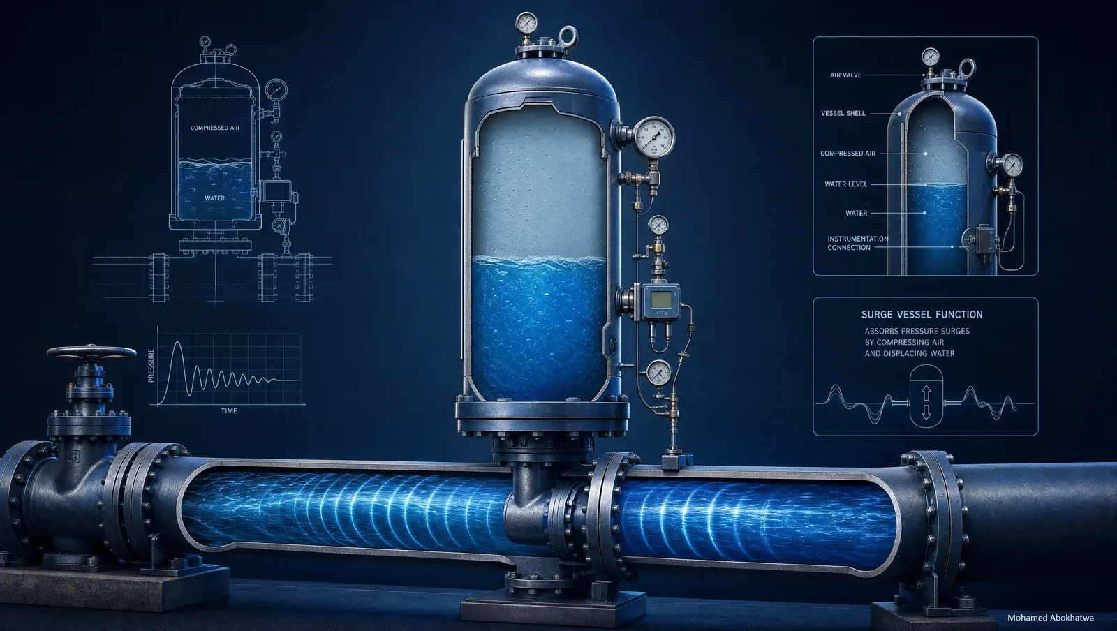
1. How the Surge Vessel Works
The surge vessel is a closed pressure vessel, partially filled with water and partially with compressed gas (nitrogen), connected directly to the pipeline near the pump station discharge. When a pump trip occurs:
- Phase 1 — Down-surge: Pressure drops. The vessel expels water into the pipeline to prevent column separation and sub-atmospheric pressures.
- Phase 2 — Up-surge: The returning pressure wave compresses the gas cushion, absorbing the excess pressure rise and preventing over-pressurisation.
2. The Governing Equation — Polytropic Gas Law
3. System Description
| Parameter | Value | Notes |
|---|---|---|
| Pipeline length | 12,000 m | Single main pipeline |
| Pipe diameter | DN 800 mm | Ductile Iron, Class K9 |
| Design flow rate | 2,520 m³/h | Peak daily demand |
| Design velocity | 1.4 m/s | Within recommended range |
| Wave speed | 1,050 m/s | DI pipe, per Chaudhry (2014) |
| Static head at pump discharge | 85.0 m | From steady-state model |
| Pipe class rating | PN 16 — 160 m head | Max allowable: 136 m (15% margin) |
| Minimum allowable pressure | +3.0 m gauge | Above vapour pressure |
| Polytropic exponent (n) | 1.2 | Standard for water transmission |
4. Baseline Simulation — No Protection
Before sizing any protection device, the first step is always to run the unprotected scenario — to establish baseline transient severity and justify the protection investment to the client.
| Location | Steady-State (m) | Max Transient (m) | Min Transient (m) | Status |
|---|---|---|---|---|
| 0 m — Pump discharge | 85.0 | 217.5 | −8.2 | FAIL |
| 6,000 m — Midpoint | 64.9 | 154.8 | −24.1 | FAIL |
| 12,000 m — Delivery | 44.8 | 96.7 | +2.1 | MARGINAL |
Figure 1 — Pressure envelope: unprotected scenario
5. Surge Vessel Sizing — Step-by-Step
1Steady-state conditions
P₀ = 85.0 m + 10.3 m atmospheric = 1.84 bar abs at the vessel tap point — not at the pump discharge head.
2Allowable pressure limits
P_max = 136 m (PN 16 minus 15% margin) | P_min = +3.0 m gauge (confirmed with client)
3Analytical starting point
4Simulation iteration
| Run | Vessel (m³) | Max Head at Pump (m) | Min Head at Midpoint (m) | Result |
|---|---|---|---|---|
| Run 1 | 4.0 | 168.4 | −6.3 | FAIL |
| Run 2 | 6.0 | 141.2 | +0.8 | FAIL |
| Run 3 | 8.0 | 128.6 | +4.2 | PASS ✓ |
6. Final Results — 8.0 m³ Vessel
| Location | Steady-State (m) | Max Transient (m) | Min Transient (m) | Status |
|---|---|---|---|---|
| 0 m — Pump discharge | 85.0 | 128.6 | +18.4 | OK ✓ |
| 6,000 m — Midpoint | 64.9 | 108.2 | +4.2 | OK ✓ |
| 12,000 m — Delivery | 44.8 | 74.1 | +8.2 | OK ✓ |
Figure 2 — Pressure envelope: unprotected vs. protected with 8.0 m³ vessel
Figure 3 — Pressure vs. time at pump discharge
7. Critical Design Parameters Often Overlooked
7.1 Pre-charge pressure
Must match the steady-state HGL at the vessel connection — not the pump head. On long pipelines, these can differ by 10–30 m.
7.2 Connection pipe diameter
7.3 Asymmetric throttle orifice
Larger orifice for outflow (fast delivery during down-surge) and smaller orifice for inflow (controlled return during up-surge to prevent slam).
7.4 Minimum water reserve
Minimum reserve = 10–15% of total vessel volume. Low-level alarm and automatic refill valve are mandatory.
7.5 Vessel location
Most effective within 50–100 m of the pump station discharge.
8. Sensitivity Analysis
| Parameter Change | Effect on Required Volume | Sensitivity |
|---|---|---|
| P₀ increases by 10% | +18–25% larger vessel | High |
| P_min tightened (3 m to 1 m gauge) | +20–30% larger vessel | High |
| Pipeline length doubled (12 to 24 km) | +40–60% larger vessel | High |
| DI replaced with HDPE | ~35% smaller vessel | Medium |
| Connection pipe reduced (DN 250 to DN 150) | Under-performs — increase 15–20% | Medium |
| Polytropic exponent: n=1.0 vs n=1.4 | ±8–12% variation | Low |
9. Final Vessel Specification
| Parameter | Value |
|---|---|
| Total vessel volume | 8.0 m³ |
| Initial gas volume (V₀) | 4.0 m³ (50% gas ratio) |
| Pre-charge pressure (P₀) | 1.84 bar abs |
| Maximum operating pressure | 16 bar (vessel shell rated PN 25) |
| Gas type | Nitrogen (N₂) — inert, no oxidation risk |
| Connection pipe diameter | DN 250 mm (≥ 0.3 × DN 800) |
| Connection pipe length | Max 5 m |
| Throttle orifice — outflow | DN 200 mm (unrestricted) |
| Throttle orifice — inflow | DN 100 mm (controlled) |
| Minimum water reserve | 0.8 m³ (10% of vessel) |
| Low-level alarm setpoint | 15% of vessel volume |
| Vessel location | Within 30 m of pump discharge header |
10. Conclusion
Surge vessel sizing is an iterative design process. The analytical method provided 6.0 m³ as a starting point — simulation confirmed 8.0 m³. Key lessons:
- Always run the unprotected baseline first to quantify the risk
- Pre-charge pressure must reflect the actual HGL at the tap point
- Connection pipe diameter directly affects vessel response speed
- The pressure-time trace at pump discharge is the single most important output for client reporting
References
- Chaudhry, M.H. (2014). Applied Hydraulic Transients, 3rd ed. Springer.
- Wylie, E.B. and Streeter, V.L. (1993). Fluid Transients in Systems. Prentice Hall.
- Thorley, A.R.D. (2004). Fluid Transients in Pipeline Systems, 2nd ed. Professional Engineering Publishing.
- Bentley Systems (2023). Bentley HAMMER V8i — User Guide. Bentley Systems Inc.
- AWWA M11 (2017). Steel Pipe — A Guide for Design and Installation.
- AWWA M51 (2017). Air-Release, Air/Vacuum, and Combination Air Valves.
- BS EN 805 (2000). Water supply — Requirements for systems outside buildings.