Introduction
In hydraulic transient analysis, simulation accuracy depends on proper boundary conditions. When modeling water infrastructure — from Strategic Water Transmission Lines to SWRO Desalination Plants — engineers must choose between modeling storage as a Reservoir or Tank. Though visually similar in the model, their mathematical behavior through the Method of Characteristics (MOC) differs significantly.
1. The Reservoir: The Infinite Anchor
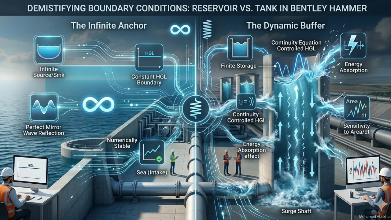
A Reservoir represents an infinite source or sink defined by a constant Hydraulic Grade Line (HGL) that remains unchanged regardless of flow magnitude during transient events.
Key Characteristics
- Analytical Behavior: Acts as a fixed reference point — Head remains constant
- Perfect Reflection: Pressure waves reflect with equal magnitude but opposite sign; high-pressure waves reflect as low-pressure waves
- Design Application: Seawater intakes, massive ground reservoirs (>50,000 m³), or any boundary where water level fluctuation during a 2-minute surge is negligible
2. The Tank: The Dynamic Buffer
A Tank is a finite storage element where water level fluctuates based on net flow — a Variable Head Boundary Condition.
Key Characteristics
- Analytical Behavior: HGL changes per continuity equation — level change = net flow × time step / surface area
- Energy Absorption: Unlike reservoirs, tanks absorb energy; reflections are "elastic" as the boundary reacts to waves
- Design Application: Elevated Storage Tanks (EST), or Surge Tanks specifically designed for protection
3. Comparative Analysis
| Aspect | Reservoir | Tank |
|---|---|---|
| Mathematical Type | Fixed Boundary (Dirichlet) | Dynamic Boundary |
| Hydraulic Grade | Constant HGL | Time-varying HGL |
| Numerical Stability | Extremely Stable | Sensitive to Area and Time Step |
| Wave Interaction | Total Reflection with sign inversion | Partial Damping |
| Data Requirements | Elevation only | Elevation, Area, Min/Max levels |
4. Practical Examples in Large-Scale Projects
Case A: SWRO Intake Basin → Use Reservoir
For desalination plant intakes, even concrete basins typically have surface areas so large that a pump trip losing 2 m³/s won't drop levels more than millimeters during the critical first 30 seconds. Reservoirs provide stable baselines for calculating vapor cavitation at pump discharge.
Case B: Top-Hill Surge Tank → Use Tank
On strategic lines crossing mountains, open-top Surge Tanks prevent column separation. Tank elements are mandatory because water column oscillation inside the tank provides the protection. Models must calculate how rapidly level rises to prevent overflow.
5. The "Numerical Instability" Warning
References
- Walski, T. M., et al. Advanced Water Distribution Modeling and Management. Bentley Institute Press.
- Chaudhry, M. H. Applied Hydraulic Transients. Van Nostrand Reinhold.
- Bentley Communities (HAMMER Knowledge Base): Modeling Neighboring Reservoirs vs. Tanks
- Thorley, A. R. D. Fluid Transients in Pipeline Systems. ASME Press.