Introduction
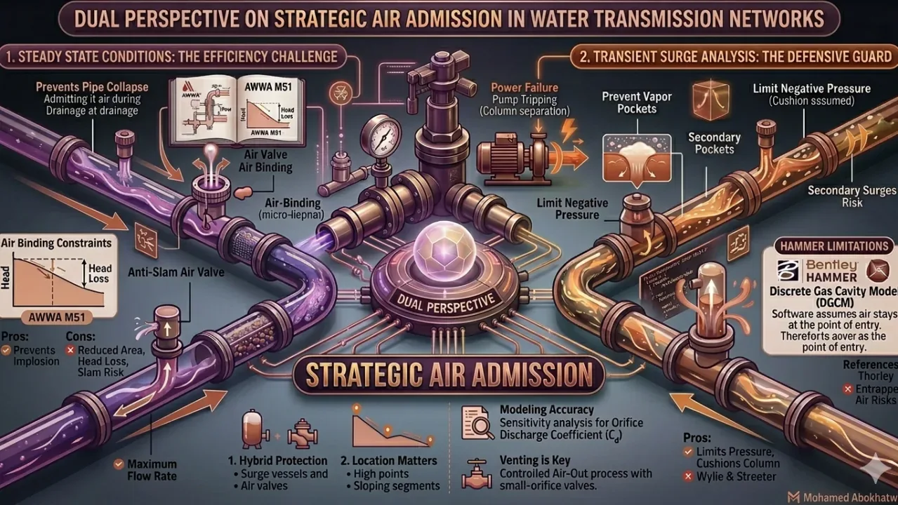
A critical paradox exists in water transmission engineering: while air typically undermines hydraulic efficiency, it serves as essential protection during transient events. Understanding when air is the enemy and when it is the lifeguard is fundamental to designing reliable transmission mains.
1. Steady State: Air as the Efficiency Enemy
During normal pressurized operation, trapped air pockets cause:
- Reduced effective cross-sectional area, increasing head loss
- "Air Binding" — flow throttling that mimics increased friction
- Hydraulic grade line distortions affecting pressure distribution
Design of Double-Acting Air Valves must account for the Large Orifice for vacuum relief during drainage, and the Small Orifice for continuous dissolved air release during pressurized operation.
2. Transient Surge: Air as the Defensive Guard
During power failures (pump trips), rapid air admission prevents:
- Vapor pocket formation at high points along the pipeline profile
- Column separation — where the water column physically separates and rejoins with catastrophic impact forces
- Pipe buckling from sub-atmospheric pressure in large-diameter thin-walled pipes
Critical Design Driver: The critical vacuum pressure of the pipe material determines air valve sizing — not arbitrary flow percentages.
3. Software Limitation: Bentley HAMMER Air Modeling
HAMMER utilizes the Discrete Gas Cavity Model (DGCM), which assumes air stays at the point of entry (the node). It does not track air slug movement or downstream migration through the pipeline. This means:
- Entrapped air migration must be assessed manually by experienced engineers
- Sensitivity analysis varying Orifice Discharge Coefficient (Cd) is essential
- Exercise conservatism — models may underestimate air pocket compression delays
4. Comparative Analysis
| Condition | Air Role | Design Priority |
|---|---|---|
| Steady State (Normal Operation) | Enemy — increases head loss | Continuous dissolved air release via small orifice |
| Filling / Re-commissioning | Must be controlled exhaust | Large orifice with anti-slam feature |
| Pump Trip / Power Failure | Ally — prevents column separation | Large kinetic orifice for rapid admission |
| Pipeline Burst (Emergency) | Critical — prevents collapse | Full-bore vacuum breaking capability |
5. Engineering Recommendations
- Hybrid Protection Strategy: Combine air valves with surge vessels/tanks when required air volume would be excessive
- Strategic Placement: Focus on high points, long downward slopes, and areas where HGL drops below pipe elevation
- Controlled Venting: Ensure Air-In is always paired with controlled Air-Out through properly sized small-orifice air release valves
- Modeling Conservatism: Perform sensitivity analysis on Cd values; account for air pocket compression delays
References
- AWWA M51: Air-Release, Air/Vacuum, and Combination Air Valves
- Thorley (2004). Fluid Transients in Pipeline Systems.
- Wylie, E.B. & Streeter, V.L. Fluid Transients.