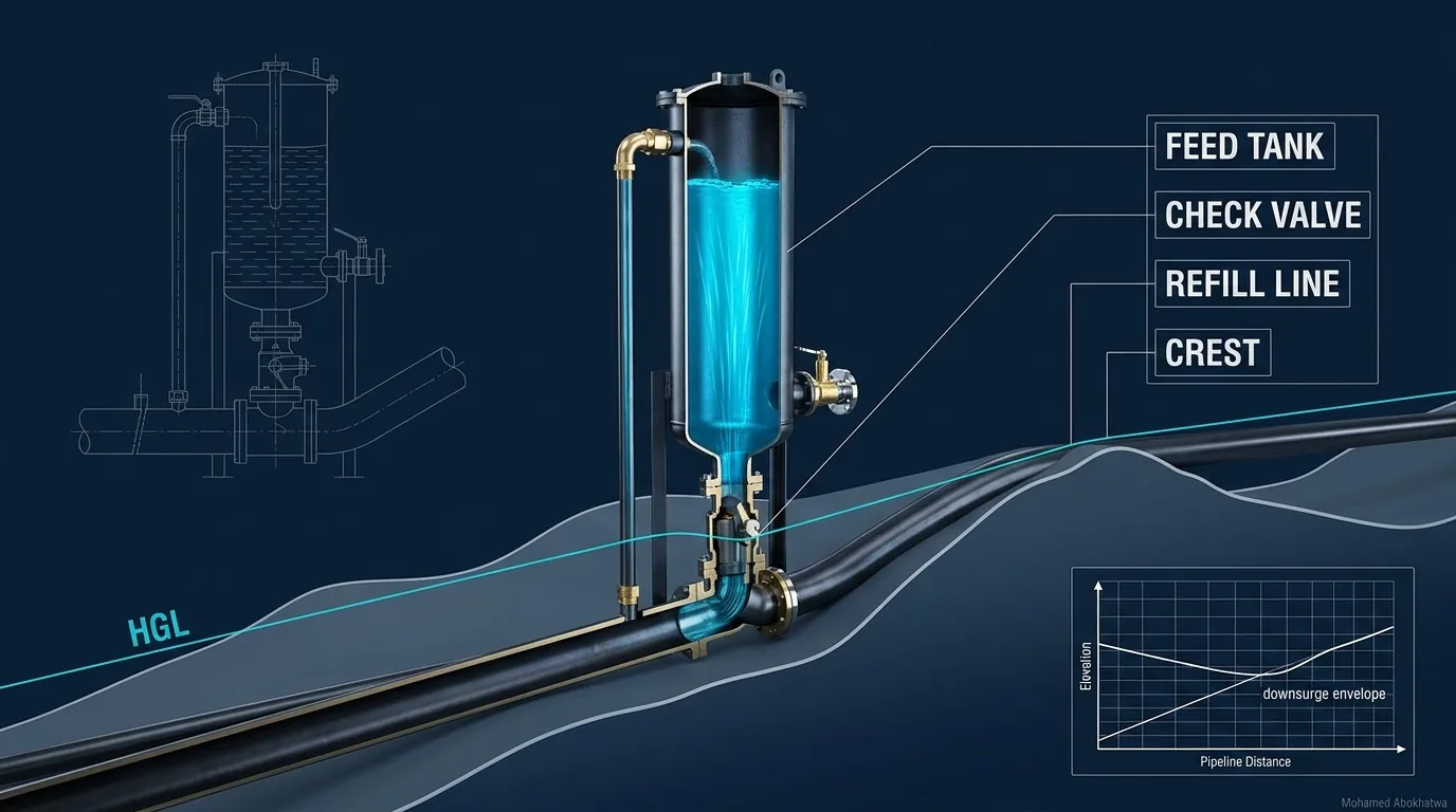
On a main that climbs out of the pump station and then runs level, the point that governs the surge protection after a power cut is not the pump but the knee, where the climb turns flat. On our 12 km DN800 example, a surge vessel that holds the knee at +3.0 m on its own needs 43.1 m³ of gas in a 104.5 m³ shell. Put a low one-way tank at the knee, its water 8 m above the pipe behind a check valve, and the vessel falls to 15.9 m³ of gas in a 37.8 m³ shell — 64 % smaller — for 20.7 m³ of water that the tank gives up. This article designs that pair, and shows the two ways it goes wrong: a tank set too high, and a tank asked to work alone.
1 · Why the knee is the weak point
When every pump trips at once, the flow at the station stops and a low-pressure wave leaves along the main. Its size is the Joukowsky head [1]:
That is more than the 94.8 m (85.0 + 9.8) the pump end has above vapour, so without protection the wave is cut off at vapour and the column separates. What a point on the pipe can tolerate, though, is a drop in pressure, and pressure is the HGL minus the pipe's own elevation:
Our profile climbs 30 m in its first 300 m and then runs level for 11.7 km, so the steady pressure falls from 85.0 m at the pump to 54.0 m at the knee although the HGL has dropped only 1.0 m. The knee has 51.0 m to lose before it reaches the criterion; the pump end has 82.0 m.
That matters most for a vessel at the pump. It fights the wave for the first seconds; after that the column slows as one mass, the HGL between the pump and the knee lies almost level, and the pressure at the knee is roughly the vessel's head minus 30 m:
So the vessel must still hold about 33 m when its gas is at its largest. In the vessel-alone run the knee touches +3.0 m nearly two minutes after the trip, and the pump end bottoms out at +32.7 m a few seconds later. The polytropic gas law sets the bill [2, 3]:
with \(P_0\) = 85.0 + 10.33 = 95.3 m absolute, \(P_{min}\) = 32.7 + 10.33 = 43.0 m absolute, \(n\) = 1.2 and \(\Delta V_w\) the water pushed into the line. While its pressure falls to less than half, the gas grows only \((95.3/43.0)^{1/1.2}\) = 1.94 times, and by then the vessel has delivered 40.5 m³, so it needs 40.5 / 0.94 = 43.1 m³ of gas. On the flat reference main, the site's reference vessel — 3.5 m³ of gas, same differential connection — holds +4.3 m with margin to spare: a 30 m climb in the first 300 m has multiplied the gas more than twelve times.
2 · How a one-way surge tank works
A one-way surge tank — the literature also calls it a feed tank or a discharge tank [4, 5] — is an unpressurised tank beside the main, connected through a check valve that opens only towards the pipe. Its surface stands \(h_T\) above the pipe. While the main's pressure there exceeds \(h_T\) the valve stays shut and the tank does nothing; once the downsurge pulls it below, the valve opens and the tank feeds the line at its own head:
The knee is held at the tank level for as long as water remains. When the main recovers the valve closes, and a small refill line tops the tank up. In a method-of-characteristics model it is an interior boundary with the head fixed while the tank feeds [1, 2].
Not a standpipe, and not an air valve
An open surge tank is connected freely, so its surface must stand at the steady HGL — here a column 54.0 m above the pipe, before any upsurge. The one-way tank sits far below the HGL and needs no pressure rating, but it acts at its own node: it cannot stop the first downsurge reaching the pump end, and alone it leaves the pump end at vapour, although once open its head raises the later minima on the pump side (section 8). An air valve at the knee is still worth fitting for filling, draining and venting [6], but it admits air only once the pressure falls below atmospheric, so it cannot hold +3.0 m (see air admission in networks).
The rule that limits the tank level
At rest the main settles at the level of the delivery reservoir. A tank surface above that opens its check valve and drains through the pipeline after every stop, so the level must stay below the lowest downstream HGL at rest:
Exceed it and a rigid-column estimate with the friction below the knee gives the drain rate:
A 16 m tank would drain at \(\sqrt{1.2/80}\) = 0.12 m³/s, indefinitely; the method-of-characteristics run gives 0.13 m³/s, within 3 % of the estimate.
3 · The example profile and the modelling basis
The main is the series reference with one change of profile: 12 km of DN800 ductile iron K9 [7] carrying 0.70 m³/s (2,520 m³/h, 1.39 m/s), wave speed 1,050 m/s, HGL 85.0 m at the pump and 44.8 m at the delivery reservoir, PN16, checked against 136 m allowable (the series criterion; design pressures and the surge allowance are defined in EN 805 [8]). The ground rises 30 m over the first 300 m and stays level at +30 m to the end. The load case is a power failure that trips every pump at once, the usual governing event [9] (the alternatives are compared in surge scenarios in pump stations).
| Point | Pipe elevation (m) | HGL (m) | Pressure (m) | Margin to +3.0 m (m) |
|---|---|---|---|---|
| Pump, 0 m | 0.0 | 85.0 | 85.0 | 82.0 |
| Knee, 300 m | 30.0 | 84.0 | 54.0 | 51.0 |
| Plateau, 600 m | 30.0 | 83.0 | 53.0 | 50.0 |
| Plateau, 4,400 m | 30.0 | 70.3 | 40.3 | 37.3 |
| Delivery reservoir, 12,000 m | 30.0 | 44.8 | 14.8 | 11.8 |
The transient numbers come from a method-of-characteristics model with a vapour cavity model, cross-checked with a gas cavity model and an independent second code [1, 10]: 120 reaches of 100 m, 150 s runs, pumps stopping instantly behind their check valves (the conservative case; see the flywheel article). The vessel has a DN400 differential connection, loss coefficient 2 out and 10 in (see the differential orifice), \(n\) = 1.2, and a shell of largest gas volume / 0.8. The tank is idealised: loss-free connection, constant level, 800 m³ available. Each vessel is the smallest steady gas volume, found by bisection, that keeps the whole line at +3.0 m.
4 · Worked example: four options on one profile
| Option | Line min (m) | Where | Knee min (m) | Pump-end min (m) | Line max (m) | Tank draw (m³) | Gas at max (m³) |
|---|---|---|---|---|---|---|---|
| No protection | −9.8 | from the pump | −9.8 | −9.8 | about 140 | – | – |
| One-way tank only, 8 m | −9.8 | from the pump | +8.0 | −9.8 | 160–170 | 27.5 | – |
| Vessel alone, 43.1 m³ gas | +3.0 | 300 m, the knee | +3.0 | +32.7 | 85.0 | – | 83.6 |
| Tank 8 m + vessel 15.9 m³ gas | +3.0 | 4,400 m, the plateau | +8.0 | +33.8 | 85.0 | 20.7 | 30.2 |
No protection. The line goes to vapour from the pump outwards, and the collapse peak at the pump end is about 140 m (139 m with the vapour cavity model, 141 m with the gas cavity model) — above 136 m either way.
Vessel alone. 43.1 m³ of gas expands to 83.6 m³, so the shell is 83.6 / 0.8 = 104.5 m³. The minimum lands on the knee and nothing rises above the steady 85.0 m. It works; it is simply very large.
Tank and vessel. With the knee held at +8.0 m the vessel needs only 15.9 m³ of gas, and its pump-end minimum of +33.8 m gives the expansion directly:
That is 1 − 37.8 / 104.5 = 64 % less shell. The water accounting shows why. Alone, the vessel pushes 40.5 m³ into the line. In the pair it pushes 14.3 m³ (30.2 − 15.9) and the tank supplies 20.7 m³ — 35.0 m³ in all, most of it from an open tank 8 m above the pipe instead of from compressed gas.
Tank alone. The knee is held at +8.0 m, but the pump end, 300 m down the slope behind a closed check valve, still reaches vapour and its collapse peak rises from about 140 m to 160–170 m; the far plateau, beyond 7.4 km, separates too. On this profile a one-way tank is never a stand-alone solution.
5 · Interactive: the profile and the envelopes
The red minimum HGL must stay above the green line (ground + 3.0 m) everywhere; where it lies on the grey dotted line the pipe is at vapour.
At the default — the 8 m tank with 15.9 m³ of vessel gas — the minimum HGL touches ground + 3.0 m at 4,400 m on the plateau, the knee is held at +8.0 m, the pump end at +33.8 m, and nothing rises above 85.0 m. Switch to the vessel alone and the critical point jumps back to the knee. Switch to the tank alone and open the window to 12 km: the knee stands at +8.0 m, but the red line sits on the vapour line over the first 200 m and again beyond 7.4 km, and the amber bar at the pump end spans 160–170 m, through the PN16 line.
6 · Reading it: the tank moves the critical point
With the tank in place the knee cannot fall below the tank level, so the vessel's critical point moves out along the plateau to about 4.4 km, where the tank has no say. The minimum at 4,400 m arrives at 18.7 s, just as the reflection from the delivery reservoir reaches it (12,000 m out and 7,600 m back at 1,050 m/s). The 8 m tank does not open until about 20 s, and anything it sends needs another 3.9 s to cover the 4.1 km. At every tank level tested the plateau minimum has come and gone before the tank's influence arrives, which is why the required steady gas is the same 15.9 m³ for every tank level from 4 to 14 m. The vessel is now sized for the first wave on the plateau, a far smaller job than holding the knee through the slow swing that follows.
The second lesson is at the pump end: without the vessel, the 300 m between the closed pump check valve and the tank becomes a short dead end in which the column still separates, which is why the tank alone makes the collapse there worse (section 4).
The third is that the two devices change each other's duty, so they must be modelled together [9]. The tank moves the vessel's critical point and trims its expansion; the vessel delays the moment the tank opens from under a second to about 20 s and cuts its draw from 27.5 to 20.7 m³. Size either one alone and you size it for the wrong event.
7 · Interactive: at the knee, second by second
The envelopes say how low each point went; the time histories say when, and what the tank was doing.
At the default the knee sinks from its steady 54.0 m, reaches the tank level at about 20 s and stays at +8.0 m while the tank feeds; 600 m follows it down to +7.2 m, and the pump end bottoms at +33.8 m as the vessel's gas reaches its largest. The draw climbs to 20.7 m³ and is finished by about 119 s. Switch to the vessel alone: nothing stops the knee, which sinks slowly to +3.0 m while the pump end falls to +32.7 m — the slow swing the big vessel exists to carry. Switch to the tank alone: it opens within the first second and holds the knee, but the pump end sits at vapour and the tank gives 27.5 m³.
8 · Sizing the tank and the vessel together
Repeating the vessel bisection at different tank levels gives the trade-off. The draw is given at 150 s and in full, from the same solver run continued to 600 s.
| Tank level above pipe | Vessel gas (m³) | Gas at max (m³) | Shell (m³) | Draw in 150 s (m³) | Complete draw (m³) | Critical point |
|---|---|---|---|---|---|---|
| No tank | 43.1 | 83.6 | 104.5 | – | – | knee, 300 m |
| 4 m | 15.9 | 32.3 | 40.3 | 14.0 | 14.0 | 4,400 m |
| 8 m | 15.9 | 30.2 | 37.8 | 20.7 | 20.7 | 4,400 m |
| 12 m | 15.9 | 28.3 | 35.4 | 30.7 | 33.5 | 4,400 m |
| 14 m | 15.9 | 27.5 | 34.4 | 35.7 | 51.7 | 4,500 m |
| 16 m | not valid: above the 14.8 m limit, drains at 0.12–0.13 m³/s indefinitely | |||||
First, the steady gas does not change from 4 to 14 m, for the reason given in section 6. Second, a higher tank trims the vessel only a little: the shell falls from 40.3 to 34.4 m³ because, with the knee held higher, the pump end falls less (its minimum rises from +30.5 to +39.1 m) and the gas expands less (32.3 to 27.5 m³). Third, a higher tank gives away much more water: 14.0 to 35.7 m³ in 150 s, and the 12 m and 14 m tanks are still feeding when the run ends. Run on, their draws end at 33.5 and 51.7 m³: a tank 0.8 m below the drain limit keeps feeding for several minutes while the line settles towards a rest pressure just above it.
The design consequence is to keep the tank low, but high enough above +3.0 m to leave room for its connection loss and its own surface falling as it feeds. On this profile 8 m does that: 5.0 m above the criterion, 6.8 m below the drain limit, and a draw complete in about two minutes. That is engineering judgement, not an optimum. Apply the drain limit at the lowest operating level of the delivery reservoir, the lowest rest HGL the tank will see.
The tank is then sized on the complete draw, with a safety factor on the usable volume, a dead depth of water above the outlet so that the end of the draw does not pull a vortex, and a freeboard above top water level. With the top water level at \(h_T\), the outlet must still sit above the pipe:
9 · Interactive: sizing the pair
Choose a tank level to see what it does to the vessel, then size the tank from the equation above.
At the default 8 m tank the vessel shell is 37.8 m³. With a safety factor of 2.0 on the 20.7 m³ draw, 1.0 m of dead water, a 5.0 m diameter and 0.5 m of freeboard, the tank holds 41.4 m³ usable in 3.11 m of water, stands 3.61 m tall (70.9 m³), and its surface falls 1.05 m in the trip, so the knee still sees nearly 7 m. The outlet sits 4.89 m above the pipe: a short elevated tank, or one on higher ground beside the knee. Step through the levels: the steady gas bar does not move, the shell creeps down, the draw grows fast. At 4 m the surface ends the trip barely above the criterion; at 14 m a 3.0 m diameter tank needs more water depth than the level allows, and its outlet drops below the pipe; at 16 m the tank simply drains.
10 · Tank details: connection, refill, vent, water quality and interlocks
The connection and its check valve
The modelled connection is loss-free; the real one is not. In the paired run the draw peaks at 0.61 m³/s, and each unit of loss coefficient costs \(v^2/2g\) of the tank's head at that flow: 0.24 m in a DN600 connection (2.16 m/s), 0.49 m in a DN500 (3.11 m/s). Take fitting coefficients from a handbook [11] and the valve's from its maker, keep the total small against the margin, and model it. The check valve must open fully on a small differential, close without slamming as the draw stops and the knee climbs back above tank level (in the paired run to no more than about 22 m in the ten minutes after the trip), and seal tight against the 54.0 m of the running main when the pumps restart [4] (see check valves and water hammer).
Refill, overflow and vent
Refill from the main through a small line with a float or altitude valve; refill time is \(t = V_{draw}/q\), so at 2 L/s the 20.7 m³ draw is replaced in 2.9 h, and the tank must be full before the pumps may restart. The overflow must pass the refill line's full-open flow at the highest main pressure (54.0 m at the knee while pumping), not just the 2 L/s design refill, in case the float valve fails open. The vent must pass the peak draw: the tank breathes in 0.61 m³/s of air, and a throttled vent pulls the air space below atmospheric, lowering the effective tank level by the same amount.
Water quality
Between trips the tank holds stagnant drinking water. Design the turnover in — a small continuous flow through the tank, or a scheduled drain and refill — with a sampling point for chlorine residual, a cover, screened openings, a lockable hatch, and linings, coatings and valves certified for drinking-water contact [12].
When the tank is out of service
The pair is one system. With the tank isolated, the paired vessel in its 37.8 m³ shell empties about 51 s after the trip; the line then separates from the pump end, the first 4.7 km reach vapour, and every point but the delivery end falls below +3.0 m. An emptied air-over-water vessel would also pass gas into the main, which the model does not represent. A closed isolating valve or an empty tank must therefore stop the pumps from running: in our practice a low-level switch and a limit switch on the isolating valve, interlocked with the pump starters and alarmed on SCADA (see transient analysis and SCADA).
11 · Setting it up in Bentley HAMMER
The general workflow is in the HAMMER transient workflow and HAMMER transient tips. Field names differ slightly between HAMMER versions, so follow the intent of each step [13].
- Draw the real profile: Pump with its suction Reservoir, Pipes and Junctions, and a Reservoir at the delivery end at its lowest operating level (see reservoir and tank boundary conditions). Put a node exactly at the knee (the Surge Tank in step 3). Set the Pipe wave speed field, or use the Wave Speed Calculator (see wave speed).
- Pump: pump trip (shut down) at the start of the run, inertia of pump and motor, and the check valve on the pump with its closure time. A very small inertia approximates the instant stop used here.
- Surge Tank at the knee: place a Surge Tank, set as a one-way surge tank with a check valve, as the knee node itself. Enter the tank level (8 m above the pipe, an elevation of 38.0 m on this profile) and the real tank area, so the surface falls as it feeds, and represent the connection loss as far as your version allows.
- Hydropneumatic Tank at the pump: initial gas volume 15.9 m³, gas law exponent 1.2, tank volume 37.8 m³, elevation with the initial water level at the pipe at the pump (0.0 m here, as the 95.3 m absolute gas pressure assumes), inlet orifice diameter 400 mm, minor loss coefficient 2 and ratio of losses 5. Bladder option off for an air-over-water vessel (see vessel type selection).
- Steady state: the Surge Tank must show no flow both while pumping (54.0 m in the main against an 8 m level) and at rest, with the pumps off and the delivery reservoir at its lowest level.
- Transient run options: run duration at least 150 s, longer if the tank is still feeding at the end; the computed time step and wave speed adjustment tolerance; vapour pressure and column separation on; your friction method.
- One scenario per option: no protection, tank only, vessel alone, the pair at each tank level, and the pair with the tank isolated.
- Read the results in the Transient Results Viewer: a profile (path) from pump to delivery reservoir with the maximum and minimum head envelopes against pipe elevation + 3.0 m and + 136 m; time histories at the knee, the first plateau node and the pump; the Surge Tank's flow and the Hydropneumatic Tank's gas volume.
- Check: envelopes within +3.0 m and 136 m everywhere; largest gas volume no more than 0.8 × tank volume; the Surge Tank never empties and has stopped feeding before the run ends.
- Iterate: reduce the initial gas volume until the minimum envelope just meets +3.0 m, reset the tank volume to the largest gas volume / 0.8, rerun, and move to the next tank level.
Where the unprotected or tank-only runs separate, report their maxima as ranges and never let a design depend on them (see surge analysis and risk).
12 · Design checklist
- Plot pressure, not only HGL, and read the steady margin to +3.0 m wherever a climb turns flat.
- Size the vessel alone first. If its critical point is a knee, test a one-way tank there before accepting a large vessel.
- Respect the drain limit: tank level below the lowest rest HGL at the knee, taken at the lowest delivery reservoir level.
- Keep the tank low, with margin for the connection loss and the surface fall; a higher tank trims the vessel slightly and costs much more water.
- Model tank and vessel together, resize the vessel with the tank in place, and find the new critical point.
- Never rely on the tank alone where the pump end can separate.
- Size the tank on the complete draw, with a safety factor and dead water above the outlet.
- Size connection, check valve and vent for the peak draw, and put the losses into the model.
- Size the overflow for a float valve failed open at the highest main pressure, and refill before the pumps may restart.
- Design the water quality in: turnover, sampling, screened openings, certified materials.
- Interlock the out-of-service case and model it as a scenario: the paired vessel alone may empty.
- Run the project analysis in HAMMER on the surveyed profile and quote collapse-governed peaks as ranges.
- Wave speed: the number that sets the surge
- The differential orifice: empty freely, refill slowly
- Bladder, diaphragm or air-over-water vessel
- One-way surge tanks at the knee
- Surge relief valves: what a valve at the pump can protect
- Pump inertia and the flywheel
- Choosing surge protection on one pipeline
References & standards
- Wylie, E.B. & Streeter, V.L. Fluid Transients in Systems. Prentice Hall, 1993 — Joukowsky head, method of characteristics, interior boundary conditions and the discrete vapour cavity model.
- Chaudhry, M.H. Applied Hydraulic Transients, 3rd ed. Springer, 2014 — boundary conditions for surge tanks and air chambers, and polytropic gas behaviour.
- Stephenson, D. “Simple guide for design of air vessels for water hammer protection of pumping lines.” Journal of Hydraulic Engineering (ASCE), 128(8), 2002 — air vessel gas volumes, expansion and the water a vessel must supply.
- Thorley, A.R.D. Fluid Transients in Pipeline Systems, 2nd ed. Professional Engineering Publishing, 2004 — surge-control devices including feed tanks, and the dynamic behaviour of check valves.
- Stephenson, D. Pipeline Design for Water Engineers, 3rd ed. Elsevier, 1989 — water hammer protection of pumping lines, including discharge tanks.
- AWWA M51 Air Valves: Air-Release, Air/Vacuum, and Combination — the role and limits of air valves at high points and changes of grade.
- ISO 2531 Ductile iron pipes, fittings, accessories and their joints for water applications — the DN800 K9 pipe of the reference main.
- EN 805 Water supply — Requirements for systems and components outside buildings — design pressures, maximum design pressure and surge allowance.
- Boulos, P.F., Karney, B.W., Wood, D.J. & Lingireddy, S. “Hydraulic transient guidelines for protecting water distribution systems.” Journal AWWA, 97(5), 2005 — power failure as the governing event, selection of protection devices and analysing them as one system.
- Bergant, A., Simpson, A.R. & Tijsseling, A.S. “Water hammer with column separation: a historical review.” Journal of Fluids and Structures, 22(2), 2006 — vapour and gas cavity models and why collapse pressures differ between them.
- Idelchik, I.E. Handbook of Hydraulic Resistance, 3rd ed. Begell House, 1996 — loss coefficients for the tank outlet, tee and bends of the tank connection.
- NSF/ANSI/CAN 61 Drinking Water System Components — Health Effects — certification of linings, coatings and valves in contact with drinking water.
- Bentley Systems. OpenFlows HAMMER product documentation and help — Surge Tank, Hydropneumatic Tank, pump trip, transient run options and the Transient Results Viewer.