Introduction
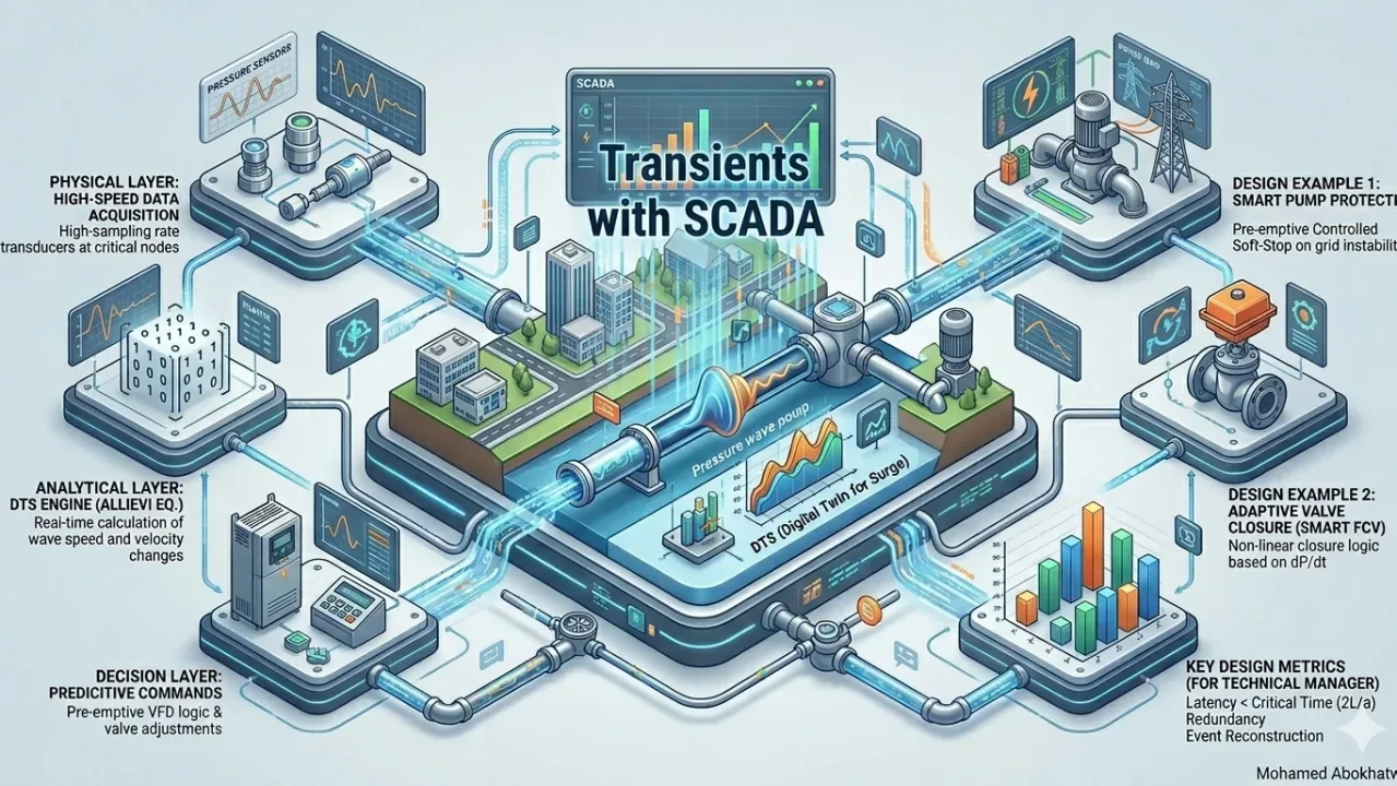
Traditional surge analysis represents a single snapshot during design phases — peak and minimum flow conditions. Real-world operations introduce complications: aging infrastructure, variable valve closure rates, and unpredictable power disruptions. The solution is the Digital Twin for Surge (DTS) — a hydraulic model integrated within SCADA systems for continuous real-time protection.
1. The Engineering Gap: Design vs. Reality
A static surge model designed at project inception may become obsolete as the system ages. Valves wear, pipeline profiles settle, and operating conditions change. The integration of transient analysis into SCADA bridges this gap — transforming a design tool into an operational safety system.
2. Technical Integration: Three-Tier Architecture
A. The Physical Layer (Data Acquisition)
High-speed pressure transducers sampling at 100 Hz or greater must be positioned at critical locations (pump stations, elevated points, line terminations). Standard SCADA sensors operating at 1 Hz cannot detect surge waves traveling at 1,000 m/s.
B. The Analytical Layer (The Digital Twin)
Real-time operational data flows into a transient calculation engine using the Allievi Equation:
C. The Decision Layer (Control Logic)
Based on predicted surge conditions, SCADA delivers Predictive Commands to VFDs and control devices to prevent pressure wave exceedance of pipe pressure class ratings.
3. Design Example: Smart Pump Station Protection
Scenario: 1200 mm steel pipeline conveying 5,000 m³/h. Risk: sudden power loss creates vacuum conditions.
- Pre-emptive Valve Control: Monitors electrical grid stability. Upon voltage deviation (prior to complete failure), initiates "Controlled Soft-Stop" through VFD DC injection braking
- Surge Vessel Monitoring: SCADA monitors the air-to-liquid proportion in surge vessels. Design curve deviations prevent pump activation during system disruption
4. Adaptive Valve Closure: The Smart FCV
Problem: Linear 60-second valve closure may still generate surge during the final 5% stroke (the "Effective Closure" zone).
SCADA Solution: An adaptive PID loop measures upstream pressure elevation continuously. When dP/dt exceeds design thresholds (e.g., 0.5 bar/sec), SCADA automatically reduces actuator velocity during final closure. This is Two-Stage Non-Linear Closure Design.
5. Key Design Metrics
| Parameter | Target | Why |
|---|---|---|
| Sensor Latency | < Tc = 2L/a | Detection must precede wave arrival |
| Control Redundancy | Dual PLC processors | Surge logic remains continuously operational |
| Sampling Rate | ≥ 100 Hz | Capture fast transients (1,000 m/s wave speed) |
References
- Bentley HAMMER / WANDA Documentation: Real-time integration modules
- AWWA Manual M51: Air-Release, Air/Vacuum, and Combination Air Valves
- Thorley, A.R.D. (2004). Fluid Transients in Pipeline Systems.
- ISA-95 Standards: Integration of Enterprise and Control Systems