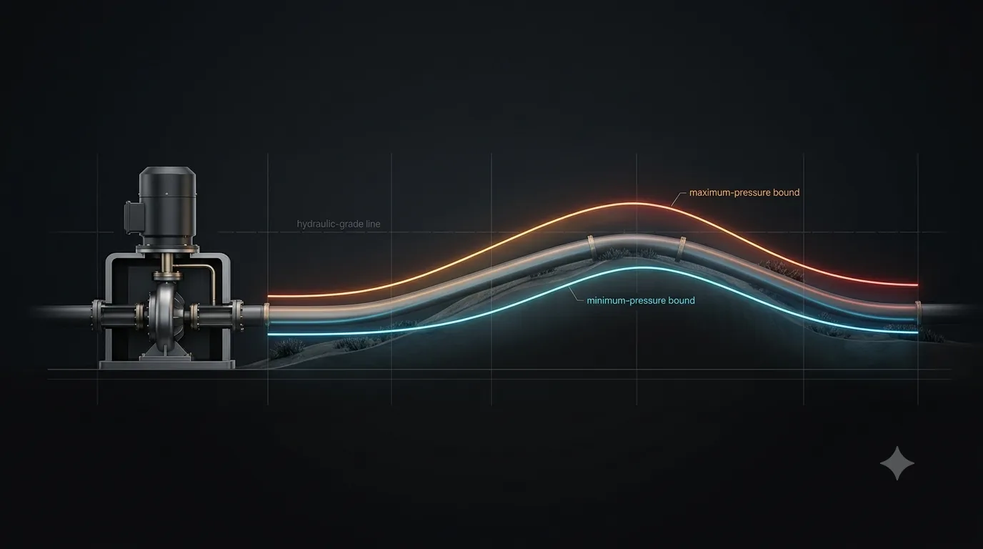
Every protection device on a pumping main is sized to a single number: the worst transient the system can credibly produce. Finding that number is a scenario problem, not a formula problem.
The transient design envelope
A pumping system is not designed against a transient — it is designed against an envelope: the highest head (maximum upsurge) and the lowest head (maximum downsurge) reached at every point along the pipeline, across all credible operating events. The two bounding lines of that envelope rarely come from the same event. The high-pressure bound protects the pipe, fittings, and pump casing against rupture; the low-pressure bound protects against column separation, pipe collapse, and the violent rejoin shock that follows a vapour cavity.
The driving physics is the Joukowsky relation — the instantaneous head rise produced when a velocity change ΔV is arrested faster than a pressure wave can travel out and back:
Whether the full Joukowsky head develops at a point depends on how the event time compares with the pipe's characteristic reflection period:
The scenario catalogue
A defensible transient study for a pumping station evaluates the following events. Each is characterised by its mechanism, whether it is voluntary (you can slow it down) or involuntary (you cannot), and which side of the envelope it tends to drive.
1 · Pump power failure (pump trip)
On loss of power, the pump's only remaining energy is the rotational inertia of the impeller and motor (GD² / WR²). The pump decelerates, head collapses at the discharge, and a downsurge wave races down the main. Flow decays, reverses, and the check valve slams shut — at which point the reversed velocity is arrested and a Joukowsky upsurge reflects back. Because power failure is involuntary and effectively instantaneous, it cannot be slowed by operating procedure. This single event is the reason surge protection exists.
2 · Pump start-up
Starting a pump against an empty or partially drained main, or starting direct-on-line, drives flow into the pipe and produces an upsurge. In modern stations this is almost always a voluntary, controllable event: soft starters, variable-frequency drives, and ramped open/close of the discharge valve limit the rate of velocity change so the disturbance time greatly exceeds Tr. Start-up rarely governs unless the control logic is crude or a pump starts against a closed system.
3 · Check-valve slam
When forward flow decays after a trip, an undamped or oversized check valve stays open until flow has already reversed. It then closes on a substantial reverse velocity, producing a sharp, localised pressure spike at the valve. This spike can locally exceed the smooth pump-trip upsurge even though it acts over a very short length. Slam is a function of valve dynamic characteristic, not pipeline length — which is why it is checked separately, and why nozzle / spring-assisted / tilting-disc check valves are specified on critical stations.
4 · Controlled and emergency valve closure
Closing an isolation or control valve arrests flow and generates an upsurge upstream and a downsurge downstream of the valve. A controlled closure (slow, programmed) is benign by definition — the closure time is set far above Tr. An emergency or spring-return closure, however, can approach rapid-closure conditions and must be analysed as a credible event, particularly on short, stiff mains where Tr is small.
5 · Single-pump trip vs. simultaneous multi-pump trip
The simultaneous trip of all duty pumps — the typical consequence of a station-wide power failure — produces the largest velocity change and therefore the deepest downsurge. A single pump tripping while others keep running is generally milder for the global envelope, but can create asymmetric local effects and reverse-flow loading on the tripped unit's check valve. Both are run; the simultaneous trip almost always bounds the minimum-pressure line.
Which scenario governs the design?
The honest answer is that no single scenario governs everything — but the responsibility is not evenly shared. The two bounds of the envelope are governed differently and predictably:
| Envelope bound | Governing scenario (typical) | Why | Protection it sizes |
|---|---|---|---|
| Minimum head (downsurge / column separation) |
Simultaneous pump power failure | Involuntary, instantaneous, largest ΔV. Cannot be slowed by control logic. | Surge vessel air volume, flywheel inertia, air/vacuum valves, pipe vacuum rating |
| Maximum head (upsurge) |
Pump-trip reverse-flow reflection or check-valve slam or emergency valve closure | System-dependent competition — long mains favour the trip reflection, short/stiff mains and poor check valves favour slam/closure. | Pipe pressure class, surge vessel sizing, check-valve type, relief valve set-point |
Two diagnostic numbers tell you in advance how the contest will resolve:
- Long main, large Tr: the pump-trip downsurge has time to develop fully and the reflected upsurge dominates — the trip tends to govern both bounds.
- Short, stiff main, small Tr: the trip is mild but any rapid valve action or check-valve slam becomes rapid relative to Tr — these govern the maximum.
Worked example: a 5 km ductile-iron pumping main
To make the contest concrete, consider a single transmission main lifting treated water from a pump station to an elevated ground reservoir. The pipeline crosses an intermediate ridge — a classic location for column separation.
System data
Step 1 — Steady velocity.
Step 2 — Joukowsky potential (full velocity arrest).
Step 3 — Characteristic period.
With Tr = 10 s, a power failure is decidedly rapid: the discharge head collapses long before any relief wave returns from the reservoir. The full Joukowsky band of ±102 m is therefore physically available at the pump — the unprotected system will both cavitate at the ridge and over-pressure the casing on reflection. This is why the three figures below all trace back to the same trip event, yet only one of them sets each design limit.
The downsurge envelope — the floor of the design
The figure below plots the minimum head reached at every point for two unprotected scenarios — a simultaneous pump trip and an emergency valve closure — against the pipe profile and the vapour-pressure limit. Where a minimum-head curve touches the vapour line, the water column separates.
The upsurge envelope — the contest for the ceiling
The maximum-head side is less tidy. Here the smooth pump-trip reflection competes with a localised check-valve slam right at the station. Both are plotted against the steady-state hydraulic grade line.
Why protection is sized to the trip — the pressure–time history
The final figure tracks head at the pump discharge through time for the governing pump-trip event, comparing the unprotected system with one fitted with a correctly sized surge vessel. This is the chart that justifies the capital cost of protection.
Acceptance criteria and code basis
Once the governing envelope is known, it is checked against allowable limits. The two bounds map onto two independent acceptance tests:
| Limit | Criterion | Basis |
|---|---|---|
| Maximum head | Peak transient head ≤ working pressure + permitted surge allowance, within the pipe's rated capacity and applicable safety factor. | AWWA C150/A21.50 (ductile iron, surge allowance) · AWWA M11 / C200 (steel) · project specification |
| Minimum head | Maintain head above vapour pressure to prevent column separation; where full vacuum is unavoidable, the pipe must be rated for it and air/vacuum valves provided. | AWWA Manual M51 (air valves) · column-separation (DVCM/DGCM) check |
| Reverse flow / slam | Check-valve dynamic characteristic selected so closure occurs at minimal reverse velocity; verify localised spike against casing and spool rating. | Valve manufacturer dynamic curves · AWWA C508/C510/C512 |
For water at ambient temperature, the vapour-pressure floor sits at roughly −10 m gauge (near full vacuum). Many KSA utility specifications (NWC, MEWA-aligned) tighten this to a practical limit such as −0.8 bar to retain a margin against separation and against thin-wall pipe collapse — a constraint that frequently drives surge-vessel sizing more than the maximum-pressure check does.
Key takeaways
- Design to the envelope, not to one event. The maximum and minimum bounds usually come from different scenarios.
- The minimum-pressure bound is almost always owned by the simultaneous pump power failure — it is involuntary, instantaneous, and produces the largest velocity change. This is the scenario that sizes your protection.
- The maximum-pressure bound is a genuine contest between the trip reflection, check-valve slam, and emergency valve closure. Slam frequently governs locally at the station even when the trip governs the line.
- Voluntary events (start-up, controlled closure) rarely govern because their rate is a design choice — slow them past Tr and they disappear from the envelope.
- The ratio of event time to Tr = 2L/a predicts the outcome before any simulation: long mains favour the trip; short, stiff mains favour valve and slam events.
References & further reading
Standards and texts that underpin the scenario set, acceptance criteria, and protection methods discussed above. Practitioners should always work to the latest published edition and to the governing project specification.
- AWWA C150/A21.50 — Thickness Design of Ductile-Iron Pipe. American Water Works Association. (Working pressure plus surge allowance and the associated safety factor for ductile-iron mains.)
- AWWA Manual M11 — Steel Water Pipe: A Guide for Design and Installation; and AWWA C200, Steel Water Pipe. American Water Works Association. (Transient pressure allowances for steel mains.)
- AWWA Manual M51 — Air-Release, Air/Vacuum, and Combination Air Valves. American Water Works Association. (Sizing and placement of air valves for column-separation control.)
- AWWA C508 / C510 / C512 — Swing-check, gate, and air-release / combination valve standards used in check-valve and reverse-flow selection.
- E. B. Wylie & V. L. Streeter, Fluid Transients in Systems. Prentice Hall. (Method of Characteristics; column separation — DVCM/DGCM; pump four-quadrant behaviour.)
- M. H. Chaudhry, Applied Hydraulic Transients. Springer. (Pump trip dynamics, surge-protection device theory, boundary conditions.)
- A. R. D. Thorley, Fluid Transients in Pipeline Systems. (Check-valve dynamic characteristics and slam.)
- Bentley Systems — OpenFlows HAMMER User Documentation (Method-of-Characteristics transient solver; scenario management, protection-device modelling). Applied Flow Technology — AFT Impulse documentation.
- BHR Group / Pump Industry guidance on surge-vessel, flywheel, and air-vessel sizing for pumping mains.
- NWC / MEWA project specifications (KSA) — applicable allowable transient pressure and minimum-pressure limits for water transmission systems.
This article is an educational discussion of methodology. It is not a design document and does not substitute for a project-specific transient analysis performed in a validated surge-modelling package.