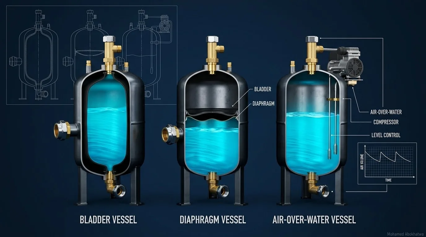
Once the transient model has fixed the gas duty, the vessel type looks like a procurement detail. It is not. On this series' reference main the duty is 3.08 m³ of gas at the steady HGL, expanding to 15.30 m³. An air-over-water vessel carries that in a 19.1 m³ shell; a bladder vessel pre-charged below the minimum pressure needs 23.2–28.4 m³ at any pre-charge from atmospheric up to 0.95 of the minimum. The bladder saves a compressor and dissolved-air losses. You pay in shell volume, a membrane that wears, and pre-charge checks that need the vessel out of service.
1 · Same duty, three machines
When the pumps trip, a vessel's compressed gas pushes water into the line until the column turns, then takes the returning water back. The duty is a statement about gas, not steel: how much gas sits in the vessel at the steady hydraulic grade line, and how far it may expand before the pressure reaches the design minimum [1]. That is the same whichever vessel carries it. What changes is the shell, what keeps the gas there between trips, and what fails.
The reference system is a 12 km DN800 ductile iron K9 main [2]: 2,520 m³/h (1.39 m/s), wave speed 1,050 m/s, 85.0 m at the pump, 44.8 m at the delivery reservoir, PN16 with 136 m allowable, and a +3.0 m minimum anywhere. With all pumps tripped and no protection, the line reaches vapour and the collapse peak is 165–190 m. A vessel at the pump with a free DN400 connection (K 0.5) holds +3.0 m with 3.08 m³ of gas at 95.3 m abs (9.35 bar abs), expanding to 15.30 m³. With a 20 % water reserve at maximum expansion, the air-over-water shell is 15.30/0.8 = 19.1 m³. The sizing method is in Sizing the Hydropneumatic Surge Vessel; this article starts where it ends.
2 · How each type holds its gas
Air-over-water
A pressure vessel partly filled with water, with compressed air above a free surface. Nothing separates gas from water, so the gas volume is whatever the level says it is. It needs a level transmitter, a compressor to add air, a vent to release it, and controls to hold the level in a band. Air dissolves under pressure, so top-up continues for as long as the vessel is in service [4], [5].
Bladder
A flexible bladder separates gas from water. Before any water enters, the gas side is charged to a pre-charge pressure and fills the whole shell. As the line comes up to pressure the bladder is squeezed into a fraction of the shell set by the ratio of pre-charge to steady pressure. No compressor, no level control, no dissolved-air loss — but the gas volume now rests on a pressure you set once, cannot see in service, and must check [5], [6].
Diaphragm
The same physics, with a membrane fixed across the shell instead of a bag. Diaphragm vessels are typically chosen for smaller volumes; everything said below about pre-charge applies to them too.
One identity ties the three together. The duty fixes a mass of gas: 3.08 m³ at 95.33 m abs is 3.08 × 95.33/10.33 = 28.4 m³ of free air. An air-over-water vessel stores it compressed, put there by a compressor. A bladder vessel pre-charged at atmospheric pressure needs a shell of exactly 28.4 m³, because the shell is the container that free air is sealed into before it is squeezed. A higher pre-charge shrinks the shell in proportion; the next section is about how high it can go.
3 · The pre-charge penalty
Between trips a bladder vessel's gas sits at ambient temperature, however quickly the line came up to pressure, so the steady state lies on the isotherm through the pre-charge. The expansion on a trip is faster (on the reference duty the gas reaches its largest volume about 46 s after the trip), so design uses a polytropic exponent n = 1.2 between the isothermal and adiabatic limits [1], [4]:
All pressures are absolute: \(V_0\) is the gas at the steady pressure \(P_0\) = 95.33 m abs, \(P_{min}\) = 3.0 + 10.33 = 13.33 m abs, \(P_{pre}\) the pre-charge and \(r\) the air-over-water reserve. The pre-charge must stay below the lowest pressure the vessel will see, or the bladder is fully expanded, and delivering nothing, before the line reaches its minimum. Write \(P_{pre} = f\,P_{min}\) and divide the two shells:
The gas volume drops out. The penalty grows with the pressure ratio, so a high-head main protected to a low minimum is the worst case for a bladder: its shell is set by isothermal charging, the air-over-water shell by the smaller polytropic expansion. Here 7.15 to the power 1/6 is 1.39, so even pre-charged at the minimum itself the bladder shell is 39 % larger than the gas at the minimum. That extra is water the bladder keeps, doing the job of the air-over-water reserve: against the air-over-water shell the penalty at f = 1 is 11 %, and the pre-charge margin adds the rest, to 23 % at f = 0.90. Simplified methods give the first estimate of an air vessel [7]; the transient model is the check.
| Vessel and pre-charge | Pre-charge (m abs) | Pre-charge (m gauge) | Shell (m³) | Gas at the minimum (m³) | Water left at the minimum (m³) | Shell vs air-over-water |
|---|---|---|---|---|---|---|
| Air-over-water, 20 % reserve (transient model) | – | – | 19.1 | 15.30 | 3.8 | – |
| Bladder, 0.60 × Pmin | 8.00 | −2.33 | 36.7 | 15.9 | 20.8 | +92 % |
| Bladder, atmospheric (0.775 × Pmin) | 10.33 | 0.00 | 28.4 | 15.9 | 12.6 | +49 % |
| Bladder, 0.80 × Pmin | 10.66 | +0.33 | 27.5 | 15.9 | 11.7 | +44 % |
| Bladder, 0.90 × Pmin | 12.00 | +1.67 | 24.5 | 15.9 | 8.6 | +28 % |
| Bladder, 0.95 × Pmin | 12.66 | +2.33 | 23.2 | 15.9 | 7.3 | +21 % |
The bladder rows use the closed-form 15.9 m³ at the minimum, slightly above the transient model's 15.30 m³: the closed form assumes the vessel itself is drawn down to +3.0 m, while in the model the line minimum occurs 4.6 km out and the vessel bottoms at 13.9 m abs (+3.6 m). The shells follow from the 3.08 m³ and the pre-charge alone, and in the transient model the 24.5 m³ bladder vessel gives exactly the air-over-water result, +3.0 m minimum and 130.9 m maximum, because the bladder never reaches the shell wall.
Now the gauge column. Every pre-charge that meets the rule and can be set by ordinary charging lies between atmospheric (f = 0.775, the 28.4 m³ free-air shell) and 0.29 bar g. The 0.60 row would need a vacuum, so with at least a 5 % margin the practical shells run from 23.2 to 28.4 m³, on a pre-charge that has to be exactly right. A transient study of one bladder shell at different pre-charges is in Pre-Charge Pressure.
4 · Interactive: shell volume by vessel type
Each bar shows what fills the shell at the lowest pressure: expanded gas, and the water still inside. The gas at the minimum is the closed form, so at the reference duty the air-over-water shell reads 19.8 m³ rather than the transient model's 19.1 m³, which is drawn dashed while the duty controls sit at the reference values.
At the reference duty the bladder shell is 24.5 m³ against 19.8 m³: 23 % larger on the same closed-form basis, and 28 % larger than the transient model's 19.1 m³. The reserves differ, though: at the minimum the bladder shell is still 35 % water, against 20 %. Push the pre-charge to 0.98 and the gap only narrows to 13 %; drop it to 0.60 and the bladder shell is 85 % larger than the air-over-water shell. Now change the system instead. Raise the steady HGL to 200 m and the penalty grows to 41 %. Bring it down to 30 m with a +20 m minimum, a low-lift main, and the bladder becomes the smaller vessel by 7 %. The pressure ratio settles part of the type decision before anyone opens a catalogue.
5 · Interactive: the gas path
The same comparison, drawn as the gas sees it. Both axes are logarithmic, so the isothermal charge is a straight line of slope −1 and the polytropic expansion a steeper one of slope −n.
The 12.00 m abs pre-charge fills 24.5 m³; charging squeezes it along the isotherm into 12.6 % of the shell; the trip expands it along the polytrope to 15.9 m³ at the minimum. Everything to the right of that point is shell you paid for and do not use. The dashed segment shows a fast expansion would have to reach 7.9 m abs before the gas filled the bladder shell; for air-over-water it ends at 10.2 m abs, where the reserve runs out. Do not count on that bladder margin. Set the exponent to 1.0 and the bladder reaches the wall exactly at the pre-charge, because in a slow drawdown the gas stays at ambient temperature — which is why we judge the pre-charge on the isothermal case, the conservative one.
6 · Air-over-water: compressors, level control and dissolved air
An air-over-water vessel is a pressure vessel plus a small process plant, and the type decision is really about the plant:
- A compressor sized for recharge, not top-up. The governing duty is recharging a vessel that has lost all its air and is full of water: 28.4 m³ of free air into a vessel at 8.33 bar g. Top-up for dissolved air is much smaller, but its rate depends on pressure, temperature and water surface and must come from the supplier or site records. For potable supply the air must be oil-free or filtered.
- Level measurement the controls can trust: a transmitter over the full working range with set points for compressor start and stop, venting, high and low alarms and a low-low alarm, brought back to SCADA.
- A vent path to release air when the water level falls too low, and a strategy for gas dissolving into the water.
- Power for compressor and instruments — remembering that a power failure is exactly the trip the vessel must ride through on the gas already inside it.
The level set points are not a controls detail; they are the surge protection. On the site's reference vessel — 20 m³ shell, 3.5 m³ of gas, DN400 differential connection (Kout 2 / Kin 10), line minimum +4.3 m and maximum 119.2 m — the transient model holds +3.0 m for any gas setting from 3.22 m³ up, only 0.28 m³ below the design setting. Above the design setting, the limit is the water reserve. The design setting expands to 16.17 m³ and leaves 3.83 m³ of water, 19 % of the shell; keeping 15 % caps the gas at 3.85 m³, 10 % at 4.28 m³, and at 5.21 m³ no water is left. A full 20 % would need 3.43 m³, just under the design setting. So the band is a few tenths of a cubic metre either side: choose the reserve to protect, then set the compressor-start level and the low-gas and high-gas alarms with the transmitter accuracy and the strapping table in front of you. How the connection shapes that envelope is in the differential orifice article.
A drained vessel is the easier case. Drain a 19.1 m³ shell with its vent open and it fills with atmospheric air that, closed and brought to the steady HGL, occupies 2.07 m³ — two-thirds of the duty. The compressor supplies only the remaining 1.01 m³ (9.3 m³ of free air).
7 · Interactive: keeping the air in
The compressor duty is a free-air calculation: the gas at the steady pressure, scaled to atmospheric, divided by the recharge time you allow.
Recharging the reference charge of 28.4 m³ of free air in two hours takes 0.237 m³/min of free air delivery; one hour doubles it to 0.474, four hours halves it to 0.118. That is an operating decision dressed as a mechanical one: how long may the station wait, unprotected, after the vessel has lost its air? The top-up slider is deliberately illustrative; whatever the real dissolution rate, the recharge sizes the machine.
8 · Interactive: when the gas setting drifts
What the level controls protect against, run through the transient model on the 20 m³ reference vessel. Each option is the gas volume the controls happened to be holding when the power failed.
At the design setting the line minimum is +4.3 m and the gas expands to 16.17 m³, leaving 3.83 m³ of water. Select 2.00 m³, a compressor that has fallen behind dissolution, and the minimum drops to −3.8 m: below the criterion, still clear of vapour. Select 4.50 m³ and the minimum improves to +7.2 m, but only 1.52 m³ of water is left at maximum expansion. Select 6.00 m³, a transmitter reading high, and the vessel empties: vapour forms at the pump end and a real vessel would pass air into the main (see air admission). The later maximum of about 96 m comes from the returning column compressing the gas, about a minute after the cavity has closed, which is why both cavity models agree. The failures sit either side of the design setting, so an air-over-water vessel needs both a low-gas and a high-gas alarm, and both drift cases belong in the HAMMER study.
9 · Bladder and diaphragm details
Checking the pre-charge
In service the bladder transmits the line pressure to the gas, so a gauge on the gas valve reads water pressure, not pre-charge. The pre-charge can only be measured with the water side isolated and drained to zero pressure. That takes an isolation valve, a drain, a period without protection or with a second vessel, and a low-range gauge that reads to a few hundredths of a bar (the setting is 0.16 bar g) — and the reading is at whatever the ambient temperature is.
Temperature
The pre-charge is a fixed mass of gas, so its pressure follows absolute temperature. Set at 20 °C, a sun-exposed vessel at 45 °C reads 318.15/293.15 = 8.5 % higher:
| Gas temperature at the check | Absolute temperature ratio | Reads (m abs) | Reads (bar g) | Fraction of Pmin |
|---|---|---|---|---|
| 0 °C | 0.932 | 11.18 | 0.08 | 0.84 |
| 20 °C (setting) | 1.000 | 12.00 | 0.16 | 0.90 |
| 35 °C | 1.051 | 12.61 | 0.22 | 0.95 |
| 45 °C | 1.085 | 13.02 | 0.26 | 0.98 |
The trap is the correction, not the heat. A technician who finds 13.02 m abs on a hot afternoon and bleeds the vessel back to the specified 12.00 has removed gas: back at 20 °C the pre-charge is 11.06 m abs and the vessel carries 2.84 m³ at the steady HGL instead of 3.08. In the transient model the line minimum moves from +3.0 m to +1.8 m. Put the reference temperature on the nameplate and a correction table in the O&M manual.
The membrane
The bladder or diaphragm is the part that wears: it flexes on every start and trip, sits permanently in the water, and must be approved for potable use under NSF/ANSI/CAN 61 [8] or the local equivalent. Specify replacement access (manway or flanged head, lifting points, headroom), the supplier's orientation, and a spare. Check the squeeze as well: the 12.00 m abs pre-charge is compressed 7.9:1 into 12.6 % of the shell in steady service, and 11.8:1 at the 130.9 m transient peak. Confirm with the supplier the pressure ratio and smallest gas fraction the membrane allows; a low pre-charge on a high-head main can exceed them. A ruptured membrane turns the vessel into an uncontrolled air-over-water vessel, its gas dissolving with no level instrument to show it. A membrane replaced and returned to service with atmospheric air instead of the specified pre-charge holds 2.65 m³ at the steady HGL, and the transient model puts the line minimum at +0.7 m: 1.67 m of forgotten pre-charge costs 2.3 m on the line.
The vessel itself
Every type is a pressure vessel designed, fabricated and inspected to EN 13445 or ASME Section VIII Division 1, within the Pressure Equipment Directive where it applies [9]; in-service inspection intervals come from national pressure-equipment regulations and the owner's inspection scheme, not from the surge study. The design pressure must cover the highest transient head at the vessel, and the line's design pressures should be checked in the EN 805 sense of maximum design pressure including surge [10]. Provide isolation and a bypass, and write down what the station may do while the vessel is out: on the reference main a trip then takes the line to vapour, with a collapse peak above PN16 (see surge risk). A vertical shell gives the level transmitter more travel per cubic metre; a horizontal one saves height.
10 · Selection by site and duty
No single criterion decides the type, and the weights depend on the site. The table gives our scores on a 1–5 scale, 5 favouring the type. They are engineering judgement, not data: re-score them for your project.
| Criterion | Air-over-water | Bladder | Diaphragm | Reason |
|---|---|---|---|---|
| Shell volume for the duty | 5 | 3 | 3 | 19.1 m³ against 23.2–28.4 m³ on the reference duty |
| No auxiliary plant | 1 | 5 | 5 | Compressor, level instruments, vent, controls and power, against none |
| Holds its gas without attention | 2 | 4 | 4 | Dissolved air needs top-up; a membrane separates gas from water, and losses show up at pre-charge checks |
| Faults visible in service | 4 | 2 | 2 | The level instrument shows lost gas in service; a lost pre-charge or torn membrane stays hidden until the next check |
| Very large volumes | 5 | 2 | 1 | A plain shell is limited by fabrication and transport; a membrane also by its manufacture; diaphragms usually suit smaller volumes |
| Remote or unmanned site | 2 | 4 | 4 | Compressors and instruments need attention and power; a membrane vessel needs periodic checks |
Water quality is pass or fail rather than scored: wetted materials need potable approval [8], and compressor air must be oil-free or filtered. Pressure-vessel inspection applies to every type; bladders and diaphragms add membrane replacement.
11 · Interactive: weighted selection
Move the weights to describe your site. Each bar is the weighted average of the table's scores, scaled to 100 and split by criterion.
The defaults describe the reference system, a large main with a staffed pump station, where shell volume, scale and visible faults matter most: air-over-water scores 73, a bladder 60, a diaphragm 56. Now describe a small unmanned booster: shell volume 2, no auxiliary plant 5, holds its gas 4, faults visible 3, large volumes 1, remote site 5. The order reverses — bladder 75, diaphragm 74, air-over-water 50 — and the shell penalty becomes a price worth paying on a site nobody visits every week. The matrix does not make the decision; it makes the reasons explicit enough to argue about. How the vessel compares with other devices on the same main is in Choosing surge protection on one pipeline.
12 · Setting it up in Bentley HAMMER
The vessel type changes only a few properties of the Hydropneumatic Tank element, and those are where the pre-charge mistakes happen [11]. Field names differ slightly between HAMMER versions. The general workflow is in the HAMMER transient workflow and HAMMER transient tips.
- 1. Steady state first. Pump with its check valve (see check valves in HAMMER), Pipe, and a Reservoir at the delivery end. Type 1,050 m/s into the pipe wave speed field: it is the series' design value, 3–6 % below the 1,080–1,117 m/s a thin-wall (Korteweg) calculation gives for DN800 K9, for the reasons in the wave speed article. Confirm 85.0 m at the pump and 44.8 m at the reservoir.
- 2. Add a Hydropneumatic Tank at the pump discharge header at its true elevation: tank volume, gas law exponent 1.2, inlet orifice diameter 400 mm, minor loss coefficient 0.5 and ratio of losses 1.0 for the free connection used here. The 20 m³ reference vessel's differential connection would instead take a minor loss coefficient of 2 (outflow) and a ratio of losses of 5.
- 3. Air-over-water. Bladder option off; tank volume 19.1 m³; initial gas volume 3.08 m³, the volume at the steady HGL that the level controls will hold.
- 4. Bladder or diaphragm. Tick has bladder; tank volume 24.5 m³; preset gas pressure 12.00 m abs, which is +1.67 m gauge or 0.16 bar g. Check whether your version and unit settings take it as gauge or absolute: the two differ by 10.33 m, about six times the gauge value. Then check the gas volume at the start of the run: 24.5 × 12.00/95.33 = 3.08 m³. If it is far off, suspect the pressure basis first. Near 4.36 m³, the exponent 1.2 is being applied to the charging: confirm the gas law your version uses between preset and initial state, and if it is not isothermal adjust the preset gas pressure until the initial gas volume is 3.08 m³.
- 5. Transient run options. Trip all pumps at t = 0; run duration at least 150 s, several times 2L/a = 22.9 s; time step computed from the shortest pipe and wave speeds with a tight wave speed adjustment tolerance; vapour pressure and column separation on, so a failed design shows as vapour rather than an impossible negative head.
- 6. Read the results. In the Transient Results Viewer, plot the profile (path) with maximum and minimum head envelopes against +3.0 m and 136 m. In the time history at the tank, the gas volume must stay below the tank volume with margin (15.30 in 19.1 m³ in our model); for a bladder, compare the lowest gas pressure with the preset gas pressure.
- 7. Failure scenarios. Air-over-water: initial gas volumes at the low-gas and high-gas alarm settings. Bladder: preset gas pressure at atmospheric (the forgotten pre-charge, +0.7 m in our model) and a mis-adjusted hot check. Both: vessel isolated, which on the reference main is an unprotected line with a 165–190 m collapse peak.
- 8. Record the settings behind the accepted envelope on the vessel datasheet — tank volume, initial gas volume or preset gas pressure with its basis and temperature, exponent, orifice, ratio of losses — so the equipment bought is the equipment modelled. The trip usually governs (see surge scenarios in pump stations), but run the other events before accepting it.
13 · Design checklist
- State the duty as gas, in absolute pressure: gas at the steady HGL, gas at maximum expansion, minimum-pressure basis and n (here 3.08 m³ at 95.33 m abs, 15.30 m³, 13.33 m abs, 1.2).
- Size the shell per type with its basis: air-over-water from maximum expansion plus reserve; bladder or diaphragm from V0 P0/Ppre, checked for water left at the minimum.
- Check the pressure ratio before the catalogue: a high P0/Pmin favours air-over-water; a low-head main with a high minimum removes most of the bladder's penalty.
- Write the pre-charge three ways — m abs, bar g and reference temperature — with a correction table in the O&M manual.
- Keep the pre-charge below the lowest vessel pressure in every design transient, judged on the isothermal case, with a recorded margin.
- Specify the pre-charge check: water side isolated and drained to zero pressure, a low-range gauge, an interval.
- Membrane: potable approval (NSF/ANSI/CAN 61 or equivalent), replacement access and lifting, orientation, spare, and the supplier's permissible ratio of operating pressure to pre-charge and smallest gas fraction (here 7.9:1 and 12.6 % in steady service).
- Air-over-water: compressor free air delivery for the accepted recharge time, oil-free or filtered air, transmitter range and accuracy, set points from the transient model's gas window and the water reserve you keep at maximum expansion, vent path, low-low alarm, power supply.
- Pressure vessel: code (EN 13445, ASME VIII, PED), design pressure above the highest transient head at the vessel, and whether a vacuum case applies.
- Isolation, bypass and an operating rule for the station while the vessel is out.
- Heat and frost: shade, insulation or trace heating where exposure would shift the pre-charge or freeze instruments.
- Failure runs: low gas, high gas, lost pre-charge and vessel isolated, each with its envelope reported.
- Wave speed: the number that sets the surge
- The differential orifice: empty freely, refill slowly
- Bladder, diaphragm or air-over-water vessel
- One-way surge tanks at the knee
- Surge relief valves: what a valve at the pump can protect
- Pump inertia and the flywheel
- Choosing surge protection on one pipeline
References & standards
- Wylie, E.B. & Streeter, V.L. Fluid Transients in Systems. Prentice Hall, 1993 — method of characteristics, the air vessel boundary with a polytropic gas law, and column separation.
- ISO 2531 Ductile iron pipes, fittings, accessories and their joints for water applications — the DN800 K9 pipe of the reference system.
- Bergant, A., Simpson, A.R. & Tijsseling, A.S. “Water hammer with column separation: a historical review.” Journal of Fluids and Structures, 22(2), 2006 — discrete vapour and gas cavity models, and why collapse peaks depend on the cavity model.
- Chaudhry, M.H. Applied Hydraulic Transients, 3rd ed. Springer, 2014 — air chambers, and the gas law exponent between the isothermal and adiabatic limits.
- Thorley, A.R.D. Fluid Transients in Pipeline Systems, 2nd ed. Professional Engineering Publishing, 2004 — surge control devices, including gas-charged vessels of different types and their practical requirements.
- Boulos, P.F., Karney, B.W., Wood, D.J. & Lingireddy, S. “Hydraulic transient guidelines for protecting water distribution systems.” Journal AWWA, 97(5), 2005 — hydropneumatic tanks among the protection strategies for water systems, and design considerations for their use.
- Stephenson, D. “Simple guide for design of air vessels for water hammer protection of pumping lines.” Journal of Hydraulic Engineering (ASCE), 128(8), 2002 — closed-form first estimates of air vessel size, checked by transient analysis.
- NSF/ANSI/CAN 61 Drinking Water System Components — Health Effects — approval of membranes, linings and other wetted materials for drinking water.
- EN 13445 Unfired pressure vessels; ASME Boiler and Pressure Vessel Code, Section VIII, Division 1; Pressure Equipment Directive 2014/68/EU — design, fabrication and inspection of the vessel shell.
- EN 805 Water supply — Requirements for systems and components outside buildings — design pressures of the pipeline, including the surge allowance in the maximum design pressure.
- Bentley Systems. OpenFlows HAMMER product documentation and help — the Hydropneumatic Tank element (bladder option, preset gas pressure, initial gas volume, gas law exponent, ratio of losses), transient run options and the Transient Results Viewer.