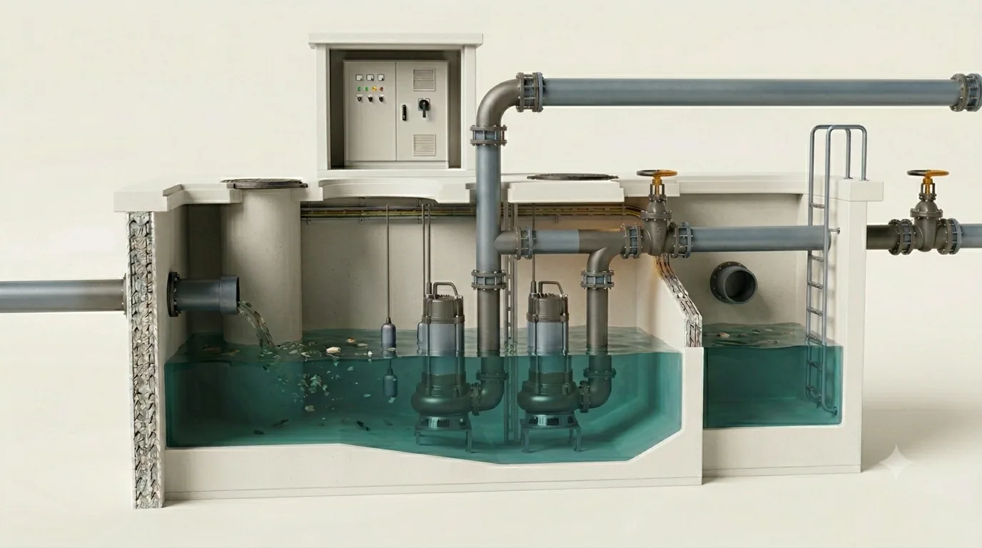
A clean-water pump is selected for efficiency. A wastewater pump is selected to keep running — through rags, wipes, grit and grease — and only then for efficiency. Get that order wrong and the station's true cost is measured in blocked impellers, midnight call-outs and septic force mains.
1 · Wastewater flips the design priorities
Everything in this station fights you. The fluid carries stringy solids that braid themselves into ropes around impeller vanes, grease that congeals on every surface above the waterline, and grit that settles in any corner where velocity drops. The flow arrives in daily waves you do not control, so the pumps start and stop all day instead of holding a duty point. And whatever sits still for too long — in the wet well or in the force main — turns septic and produces H2S, which destroys concrete and announces the station to the neighbourhood.
Hence the design order of a wastewater station, which this article follows:
- An impeller that will not clog on the solids actually arriving — accepting an efficiency penalty with open eyes (Sections 2–3).
- A force main that scours itself at least once a day, so grit and grease never accumulate (Sections 4–5).
- A wet well sized for the motors — enough active volume that pumps don't cycle to death, small enough that sewage doesn't sit and turn septic (Sections 6–7).
- Geometry that cleans itself, because anything that needs a vacuum truck monthly was designed wrong (Section 8).
2 · Impeller selection — buying clog resistance with efficiency
Every wastewater impeller is a compromise between three things: hydraulic efficiency, free solids passage (the largest sphere that passes through), and rag handling (resistance to stringy material wrapping the leading edges). The main families:
| Impeller | Typical η | Free passage | Character |
|---|---|---|---|
| Two-vane non-clog (closed channel) | 70–80% | ~75–100 mm | The workhorse for municipal sewage; good η, decent passage; rags can still bridge two leading edges |
| Single-vane non-clog | 65–75% | ~80–100 mm | One continuous channel — better rag passage than two-vane, slightly lower η, higher unbalance (bearing care) |
| Screw-centrifugal | 75–85% | ~75–100 mm | Single helical vane "screws" solids through; excellent rag handling and high η; gentle on solids; premium price |
| Vortex (recessed) | 35–50% | ≈ full branch bore | Impeller sits out of the flow path — solids barely touch it; nearly unclogable and grit-tolerant; pays ~30 efficiency points for it |
| Chopper / grinder | 50–65% | cuts instead of passing | Cutting elements shred rags and wipes; for wipes-heavy catchments and small-bore rising mains; sharpening is a maintenance item |
Two selection rules anchor the choice. First, the regulatory floor: pumps handling raw sewage should pass a 75 mm (3 in) sphere as a minimum — the long-standing Ten-State Standards requirement[2]. Second, match the impeller to the catchment, not the catalogue: a gravity-fed municipal station with upstream screening can run efficient channel impellers; an unscreened station serving a community generous with wipes needs screw-centrifugal, vortex or chopper hydraulics, and the energy bill of that choice should be computed, not feared.
3 · Interactive: the price of clog resistance
At the default duty the vortex choice costs ≈ $2,750/yr more in electricity — about $32,000 in present value over 20 years. If upstream screening or a screw-centrifugal impeller can handle the catchment's solids reliably, that is the prize. If the station clogs twice a month, $2,750 is the cheapest insurance you will ever buy.
4 · The force main — design for scour, check for septicity
A wastewater force main has a hydraulic requirement no clean-water main has: it must resuspend and flush out its own sediment. Grit settles whenever velocity drops below roughly 0.6 m/s; grease films grow in sluggish mains. The classic criteria[2,3]:
- v ≥ 0.6 m/s (2 ft/s) — minimum to keep sewage solids moving; must be reached at least once per day, every day.
- v ≈ 1.0–1.1 m/s (3.5 ft/s) — re-suspension velocity: flushes grit that settled during low-flow periods. Good practice is to reach this regularly (e.g. during peak pumping or a deliberate flushing cycle).
- v ≤ ~2.4–3.0 m/s — above this, friction and surge pressures climb steeply and energy is wasted; check transients explicitly (see surge scenarios in pumping stations).
The diameter decision is therefore a squeeze from both sides: too large and the main never scours (grit bed, grease, rising friction, septicity); too small and friction devours energy and surge margins. Worked example: a duty of 60 L/s in DN200 gives \(v = 0.060/0.0314 = 1.91\) m/s — comfortably scouring, ~20 m/km of friction. The same flow in DN300 gives 0.85 m/s: it never reaches re-suspension velocity, and the "conservative" larger pipe quietly becomes a grit trap. The minimum daily flow matters as much as the peak: this station must also push ≥ 28 L/s (the 0.9 m/s flow in DN200) at least once a day.
5 · Interactive: force-main velocity checker
Try the "conservative" mistake: keep 60 L/s and step the diameter up to DN300 — velocity falls to 0.85 m/s, permanently below the re-suspension band. In force mains, oversizing is not conservative; it is a sedimentation design. Size for scour at the everyday flow, then verify friction and surge at peak.
6 · The wet well — active volume and the cycle-time law
A fixed-speed pump in a wet well lives by a simple, brutal rhythm: the well fills, the pump starts, draws the level down, stops, and the well fills again. Too small an active volume and the pump starts so often it cooks its motor and contactor. Too large and sewage sits long enough to go septic. The mathematics is one of the most elegant results in station design.
With pump capacity \(Q_p\) and steady inflow \(q\), one cycle takes the fill time plus the draw-down time of the active volume \(V\):
The cycle is shortest when inflow equals exactly half the pump capacity — the worst case the design must survive. If the motor allows \(Z\) starts per hour (cycle time \(T_{min} = 3600/Z\) seconds), the minimum active volume follows directly:
Worked example: one duty pump at \(Q_p\) = 60 L/s, motor rated for 10 starts/hour → \(T_{min}\) = 360 s → \(V_{min} = 360 \times 0.060 / 4 = \) 5.4 m³ of active volume between start and stop levels. Check the other side: at half-capacity inflow (30 L/s) the well turns over in \(5.4/0.030 = \) 180 s — fresh sewage, no septicity. Both constraints satisfied with metres to spare.
| Motor size | Typical starts/hour | Min cycle time |
|---|---|---|
| Small submersible ≤ 15 kW | 12–15 | 4–5 min |
| 15–90 kW | 8–10 | 6–8 min |
| > 90 kW, soft-start / large dry-pit | 4–6 | 10–15 min |
Three refinements every real design adds: alternation of duty pumps multiplies the allowable station starts (two alternating pumps ≈ half the starts each); staggered stop levels for lag pumps prevent simultaneous cycling; and a VFD changes the problem entirely — at variable speed the pump tracks inflow instead of cycling, and the wet well can shrink toward its septicity-optimal minimum (but verify the force main still sees its scouring velocity at reduced speed — the trap covered in the VFD myth).
7 · Interactive: cycle time & active volume
Notice the shape: cycle time rises steeply toward very low and very high inflow — the dangerous zone is the broad middle. This is why "the station is fine at night and fine at peak" proves nothing: the killing inflow is half the pump capacity, which most stations cross twice a day, every day.
8 · Self-cleaning design — geometry does the maintenance
Whatever the level controls do, solids obey the geometry. A wet well that accumulates grease mats and grit cones was shaped wrong on the drawing board:
- Benching: slope the floor at 45–60° toward the pump inlets, with no horizontal shelf anywhere below top water level. Flat floor = grit beach.
- Minimum floor footprint: the smaller the wetted floor, the higher the local velocities and the less material settles — the active volume should come from depth and the level range, not from a generous plan area.
- Inlet placement: drop the incoming sewer where it will not aerate the pump suction or fire a jet across it (free-fall entrains air; air in a sewage impeller means lost capacity and noise). Baffle if the geometry forces a bad angle — and check the suction conditions exactly as in the wet-well vortex article.
- Submergence: respect the ANSI/HI 9.8 minimum, \(S = D(1+2.3\,Fr_D)\), at the lowest pumping level[1] — vortex-swallowed air is capacity lost precisely when the well is nearly empty and you need the pump most.
- Trench-type wet wells (HI 9.8 Appendix): a narrow trench under the pumps with steep side walls, designed to be pump-down cleaned — periodically running the last pump below normal stop level so the trench velocity sweeps accumulated solids into the pump. One automated purge cycle a day replaces the vacuum truck.
- Grease management: the start/stop level band itself scrubs the walls — a wider operating band passes the waterline over more wall area; combine with washdown provisions at stations receiving restaurant catchments.
9 · Design checklist
- Impeller: ≥ 75 mm sphere passage minimum; choose the family from the catchment's solids load and screening, then price the efficiency gap over 20 years — both directions.
- Redundancy: N+1 with automatic alternation; peak inflow met with the largest unit out of service.
- Force main: ≥ 0.6 m/s daily, ≈ 1.0 m/s regularly for re-suspension, surge-checked at the top end; travel time computed against septicity; sewage-rated air valves at the profile's high points.
- Wet well volume: \(V_{min} = 900\,Q_p/Z\) per duty pump, then verify turnover time at average inflow stays within the septicity budget.
- Levels: stop level above HI 9.8 submergence; start levels staggered; alarm and overflow levels with genuinely usable freeboard volume.
- Geometry: benched floor, minimum footprint, controlled inlet entry, and a pump-down cleaning routine designed in — not retrofitted.
- Controls: alternation, anti-cycle timers, minimum-run timers; if VFD, verify force-main scour velocity at minimum speed.
- Maintainability: guide-rail lifting clear of the benching, davit reach over each pump, isolation on both sides of every check valve — the best hydraulic design fails if nobody can lift the pump.
References & standards
- Hydraulic Institute. ANSI/HI 9.8 — Rotodynamic Pumps for Pump Intake Design (wet-well geometry, submergence, trench-type wet wells).
- GLUMRB. Recommended Standards for Wastewater Facilities ("Ten-State Standards") — solids passage, velocities, wet-well detention.
- Water Environment Federation. Design of Wastewater and Stormwater Pumping Stations, WEF Manual of Practice No. FD-4.
- Jones, G.M. (ed.). Pumping Station Design, 3rd ed. Butterworth-Heinemann, 2008 — cycle-time mathematics, force mains, station layout.
- Metcalf & Eddy / AECOM. Wastewater Engineering: Collection and Pumping of Wastewater. McGraw-Hill.
- U.S. EPA. Design Manual: Odor and Corrosion Control in Sanitary Sewerage Systems and Treatment Plants (septicity, H₂S, retention time).
- Xylem/Flygt. Design Recommendations for Pumping Stations with Submersible Sewage Pumps (manufacturer design guide; sump geometry and cleaning functions).
- Gülich, J.F. Centrifugal Pumps, 4th ed. Springer, 2020 (impeller types and solids-handling hydraulics).
- Hydraulic Institute. ANSI/HI 9.6.3 — Rotodynamic Pumps: Guideline for Operating Regions.