Introduction
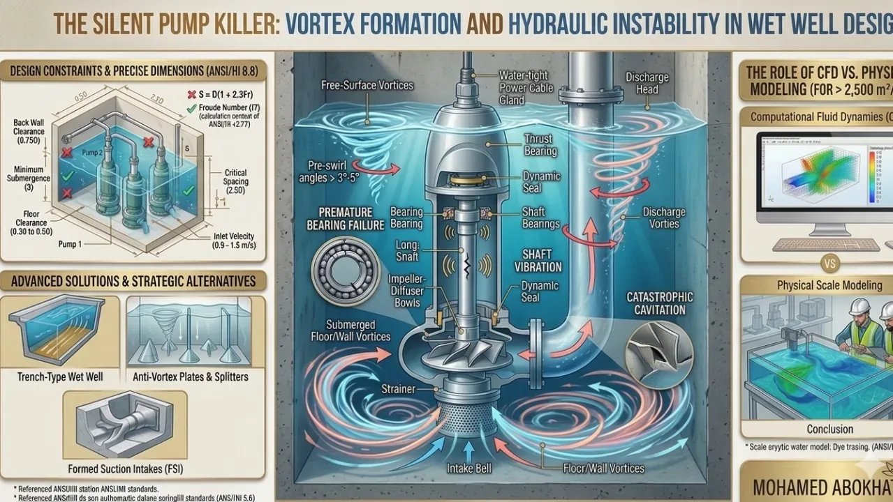
Vortex formation is one of the most underestimated threats in pump station design. In wastewater treatment plants and lift stations, undersized or poorly shaped wet wells create uneven fluid velocity — generating Free-Surface Vortices (drawing air from above) or Submerged Vortices (originating from floor or walls). The result: reduced pump efficiency, shaft vibration, and premature mechanical failure.
1. The Core Problem: Why Standard Pits Fail
The pre-swirl effect is the critical danger. Asymmetrical approach flow introduces rotational components at pump suction. Even a small swirl angle exceeding 3° to 5° significantly degrades pump efficiency and induces shaft vibration leading to bearing damage.
2. Design Constraints Based on ANSI/HI 9.8
Professional designs must adhere to these geometric constraints, where D = intake pipe diameter:
| Parameter | Requirement | Purpose |
|---|---|---|
| Inlet Velocity | 0.9 – 1.5 m/s | Prevents sedimentation without excess turbulence |
| Minimum Submergence (S) | S = D(1 + 2.3 Fr) | Prevents air-drawing free-surface vortices |
| Back Wall Clearance | 0.75D from suction bell center | Prevents stagnant zones and wall-fixed vortices |
| Floor Clearance | 0.3D – 0.5D | Prevents floor-fixed submerged vortices |
| Pump-to-Pump Spacing | Minimum 2.5D between centers | Prevents intake flow interference |
3. Advanced Solutions for High-Flow Sites
Trench-Type Wet Wells
Narrow floor toward pumps maintains scouring velocities for self-cleaning while minimizing footprint — ideal for wastewater applications.
Flow Splitters & Anti-Vortex Plates
Vertical splitter plates or cones break submerged vortex cores when submergence is borderline. Cost-effective solution for retrofit situations.
Formed Suction Intakes (FSI)
Custom concrete "scabbard" transitions flow with zero pre-swirl — the gold standard for high-capacity critical infrastructure where reliability cannot be compromised.
4. CFD vs. Physical Modeling
For flows exceeding 2,500 m³/hr per pump, static design carries significant risk:
- CFD: Essential for visualizing velocity vectors and identifying stagnant zones
- Physical Scale Modeling (1:5 to 1:10): Most reliable method for critical projects — verifies air-entrainment levels that CFD may underestimate
5. Conclusion
Designing a wet well with precise hydraulic geometry is a proactive investment in Asset Lifecycle Management. Eliminating vortex-induced stresses shifts focus from reactive maintenance to long-term operational excellence — reducing maintenance costs and extending pump service life significantly.
References
- ANSI/HI 9.8: Rotodynamic Pumps for Pump Intake Design
- ANSI/HI 9.6.6: Rotodynamic Pumps for Pump Piping
- Saffman, P. G.: Vortex Dynamics. Cambridge Monographs.
- Prosser, M. J.: The Hydraulic Design of Pump Sumps and Intakes. BHRA.