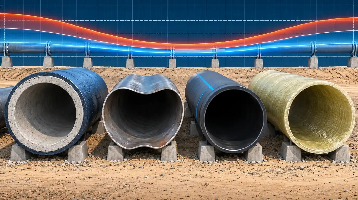
“Maximum head below PN” is how many surge results are judged, and it is too crude in both directions. On the 12 km reference main the unprotected pump trip peaks at 165–190 m (16.1–18.6 bar), above the 16 bar rating of its flanged components. Yet under EN 805 and EN 545 those components may take 20 bar during a surge, so the peak itself would pass. What fails the design is the other side of the envelope: the line falls to full vacuum, beyond the −0.8 bar that pipeline components are required to withstand. This article sets the envelope against the limits that actually apply: the EN 805 pressure terms, the allowances in each pipe material's standard, collapse under vacuum, and fatigue for plastic pipes that see recurring surges.
1 · The pressure terms that matter
EN 805 separates what the system does from what its components can take [1]. For the system, the designer fixes:
- DP, design pressure: the highest steady operating pressure of the system or zone, including future developments but excluding surge.
- MDP, maximum design pressure: DP plus surge. It is written MDPc when the surge has been calculated and MDPa when a fixed allowance is used instead; that allowance must not be less than 2 bar.
- STP, system test pressure: the hydrostatic test after laying. When surge is calculated, STP = MDPc + 1 bar. When it is not, STP is the lower of 1.5 × MDPa and MDPa + 5 bar.
The product standards rate each component with three matching terms [1][2]:
- PFA, allowable operating pressure: what the component may carry continuously. It must be at least DP.
- PMA, allowable maximum operating pressure: what it may carry for short periods, including surge. It must be at least MDP.
- PEA, allowable site test pressure: what it may see in the hydrostatic test. It must be at least STP.
For ductile iron to EN 545, PMA = 1.2 × PFA [2]. For flanged components the PN class sets the figures: PN10 is 10/12/17 bar (PFA/PMA/PEA), PN16 is 16/20/25 and PN25 is 25/30/35. The pipe barrel is usually much stronger than the flanges: a DN800 pipe in class C25 has a PFA of 25 bar. The weakest component sets the limit, and in a pumped main that is usually a valve, a flange, the vessel or an air valve, not the pipe.
On the negative side, EN 805 and the related product standards require components to withstand a transient pressure 80 kPa below atmospheric, that is −0.8 bar or −8.2 m of water [1][3]. Full vacuum, where water boils and the column separates, is about −9.8 m at ordinary temperatures. Owners often add their own limits on top: this series uses 136 m as a project maximum and +3.0 m as a design minimum [4]. Many owners accept a sub-atmospheric minimum instead, commonly around −3 m, where the pipe, joints and fittings are rated for it and every air valve that will open is modelled; it still leaves 6.8 m before vapour. Either is a legitimate choice only after it has been checked against the allowable values that actually apply: the project specification, the owner’s or utility’s standards, and the manufacturers’ ratings for every component on the line. The strictest of them governs, and the report must state the chosen minimum, its source and the reason.
2 · The reference main in EN 805 terms
The reference main is a 12 km DN800 ductile iron line with PN16 flanged valves and fittings, pumping 0.70 m³/s at 85.0 m at the pump [4]. The steady head at the pump is 85 m, but against a closed line valve the pump makes its shut-off head of 105 m (5 m suction plus 100 m), so we take DP = 105 m = 10.3 bar. With the series vessel (3.5 m³ of gas in a 20 m³ shell), the calculated maximum is 119.2 m:
| Term | How it is set | Head (m) | bar | Component limit | Check |
|---|---|---|---|---|---|
| DP | pump shut-off head | 105.0 | 10.3 | PFA 16.0 | pass |
| MDPc | calculated maximum | 119.2 | 11.7 | PMA 20.0 | pass |
| STP | MDPc + 1 bar | 129.4 | 12.7 | PEA 25.0 | pass |
| MDPa | DP + 2 bar (if surge were not calculated) | 125.4 | 12.3 | PMA 20.0 | pass |
| STP | lower of 1.5 MDPa and MDPa + 5 bar | 176.5 | 17.3 | PEA 25.0 | pass |
| Minimum | calculated lowest head | +4.3 | +0.42 | −0.8 bar | pass |
Two things follow. A calculated surge earns a lower test pressure: 12.7 bar instead of 17.3, which matters on long mains where the test pressure decides section lengths and the pump size for the test. And the vessel design is limited not by the PN16 rating but by the project's own 136 m, which is a choice about how much margin the owner wants, not a component limit. A report should say which limit it is applying and why.
3 · Interactive: one envelope, several limits
Choose a protection case and a component class, and read the envelope against each limit. Where the peak comes from cavity collapse, two cavity models give different values, so both are drawn and both are checked [5].
With no protection the peak of 164.6–189.9 m (16.1–18.6 bar) exceeds PFA but stays inside the PMA of PN16 components, while the whole line goes to vapour. With the relief valve the peak along the line is 126.7–143.3 m, inside PFA and PMA but over the project limit under one cavity model, and the line still goes to vapour. Only the vessel and the flywheel meet every limit. Switch to PN10 components and the vessel case still passes PMA (12 bar = 122.5 m against 119.2 m), but with 3.3 m to spare, which is less than the spread between cavity models on any case that cavitates.
4 · What each pipe material allows
Each material family states its surge allowance differently. These are the rules we apply, with the references; always check the current edition and the manufacturer's own rating.
| Material | Standard | Maximum including surge | Notes |
|---|---|---|---|
| Ductile iron | EN 545 [2] | PMA = 1.2 × PFA | Flanged components rated by PN; the barrel class (C25, C30, C40) is usually higher. |
| Ductile iron | AWWA C150 [6] | Working pressure plus a 100 psi (6.9 bar) surge allowance, built into the thickness design | Larger surges need a thicker class or protection. |
| Steel | AWWA M11 [7] | Hoop stress under working plus transient pressure ≤ 75 % of yield | Working pressure alone is limited to 50 % of yield. |
| Polyethylene | AWWA C906, M55 [8] | Occasional surge: total ≤ 2.0 × PC. Recurring surge: total ≤ 1.5 × PC | PC is the pressure class; temperature derating applies. |
| GRP | AWWA M45, C950 [9] | Working plus surge ≤ 1.4 × PN | Commonly stated by manufacturers; confirm with the supplier. |
| PVC-U, PVC-O | EN ISO 1452, AWWA C900 [10] | Per the class standard and the manufacturer | Recurring surges are checked for fatigue (section 6). |
The occasional and recurring distinction runs through all of them. A power failure that trips every pump is an occasional event: a few times a year at most. A pump start or a planned stop is a recurring one: thousands of times over the life of the main. The design envelope of a surge study is usually the occasional trip, checked against PMA or its equivalent. Recurring events are smaller but far more numerous, and for plastics they are the ones that consume the pipe (section 6).
5 · Vacuum: will the pipe collapse?
A minimum envelope at vapour pressure means the pipe wall carries about one atmosphere of external pressure. For thick ductile iron that is trivial. For thin steel, GRP and plastics it is a buckling check. For a long unrestrained pipe, the elastic critical pressure is [11][12]:
where \(t\) is the wall thickness, \(D_m\) the mean diameter and SDR the outside diameter over the wall. For GRP, rated by its ring stiffness SN = \(EI/D_m^3\) in N/m², the same expression is \(P_{cr} = 24\,SN\) per unit length. Real pipes are not perfectly round, and the ovality reduces the capacity. The factor used in the PE pipe literature for an ovality \(\delta\) is [8][12]
We then apply a safety factor, 2.0 in our practice for a short-term event. Surges last seconds, so the short-term modulus applies, reduced for temperature. A buried pipe is also supported by the soil, which raises its buckling resistance considerably; the unrestrained value applies above ground, in chambers and galleries, and in poorly compacted trench.
PE100 SDR17 allows 2.1 bar of vacuum with 3 % ovality and a factor of 2, comfortably more than full vacuum. SDR26 allows only 0.55 bar and should not be exposed to full vacuum unsupported. GRP SN5000 has a critical pressure of 1.2 bar before any reduction, so with ovality and a factor of 2 it allows 0.46 bar; SN10000 allows 0.92. A DN800 steel pipe (outside diameter about 0.81 m) needs a D/t of about 120 or less to take full vacuum on these assumptions, which is 6.7 mm of wall or more. These are the cases in which the minimum envelope, not the maximum, decides the pipe class or the protection.
6 · Fatigue: recurring surges in plastic pipes
Ductile iron and steel are rarely limited by surge fatigue in water service. PVC and PE are: each pressure cycle consumes a little of the pipe's life, and the consumption rises steeply with the size of the swing. For PVC the method recommended by the PVC pipe industry is the one developed by Folkman, used in the Uni-Bell cyclic life calculator [13]. The hoop stress amplitude and the cycles to failure are
with pressures and stress in psi. The cyclic life in years is \(N\) divided by the number of cycles per year. We divide the result by 2 as a design margin. The pressures come straight from the surge model: the maximum and minimum at the critical point for each recurring event (a normal start, a normal stop, a duty change), not the trip envelope.
A DR18 force main cycling between 1.5 and 9.0 bar 24 times a day lasts about 430 years by this method, 216 with the margin. Raise the maximum to 12 bar and drop the minimum to 0, a swing of 12 bar, and the life falls to about 60 years, 30 with the margin: short of a 50-year design life. Because life goes with the swing to the power of about 4.2, a protection device that halves the recurring swing multiplies the life roughly eighteen times. For PE, the industry's approach is the allowance in section 4: the recurring surge is kept within a total of 1.5 × PC, a level at which PE4710 pipe has been shown to last millions of cycles [8].
7 · Worked example: checking the reference main
Step 1: identify the weakest component
Pipe barrel DN800 C25 (PFA 25 bar); valves, flanges and the vessel connection PN16 (16/20/25 bar); air valves PN16. The system is PN16.
Step 2: set DP and MDP
DP = 105 m = 10.3 bar (pump shut-off). MDPc = 119.2 m = 11.7 bar from the governing trip. Both within PFA 16 and PMA 20.
Step 3: check the owner's criteria
Maximum 119.2 m against the 136 m project limit: 16.8 m of margin. Minimum +4.3 m against +3.0 m: 1.3 m of margin. The line never goes below atmospheric, so the −0.8 bar requirement is not engaged.
Step 4: check vacuum capacity anyway
If the vessel is out of service, the line goes to vapour (section 3). Ductile iron DN800 C25 is not at risk of collapse, but any thin-walled steel spools in the station and the air valves' own ratings must be checked against full vacuum, or the operating rules must forbid running without the vessel.
Step 5: set the test pressure
STP = MDPc + 1 bar = 12.7 bar, within PEA 25. Had the surge not been calculated, the test would have been 17.3 bar.
Step 6: recurring events
Ductile iron is not fatigue-limited in this service. Had the main been PVC or PE, the normal start and stop would be modelled, and their swings run through section 6.
8 · Reading the limits in Bentley HAMMER
HAMMER reports heads and pressures; the limits are yours to add [14]. Field names differ slightly between versions.
- Give every pipe its pressure rating in a user data field (PFA and PMA, or PC for plastics), and record the weakest component on each pipe, not only the barrel class.
- Plot pressure, not head, in the profile view: maximum and minimum pressure envelopes along the path, with the ground or pipe crown profile.
- Draw the limits on the profile: PMA, PFA, the project maximum, −0.8 bar, full vacuum and the design minimum.
- Use colour coding on the plan to show pipes whose maximum transient pressure exceeds their PMA, or whose minimum falls below their vacuum capacity, and check every flagged pipe.
- Check vapour pockets and cavity volumes in the results: any column separation means the maximum is model-dependent, as in the unprotected case above.
- Model recurring events separately (normal start, normal stop, duty changes) and export the pressure range at the critical points for the fatigue check.
- Report MDPc and STP from the governing envelope, so the test pressure can be set from the calculation.
9 · Checklist
- Weakest component identified on every part of the line: valves, flanges, vessel, air valves, fittings.
- DP, MDP and STP stated in EN 805 terms, with the basis of DP.
- MDP ≤ PMA, DP ≤ PFA, STP ≤ PEA for the weakest component.
- Owner's criteria applied separately and named as such.
- Minimum envelope checked against −0.8 bar, full vacuum and the collapse capacity of every thin-walled pipe.
- No acceptance resting on a collapse peak: column separation is designed out first.
- Occasional and recurring events separated, with fatigue checked for plastic pipes.
- Temperature derating applied to plastic pipe ratings.
- Is your HAMMER run right? Time step, adjustment and run duration
- Pump data for a pump trip: inertia, specific speed and four-quadrant curves
- Reading the surge envelope against the pipe's real limits
- The surge study report: what to deliver and what a reviewer checks
References & standards
- EN 805 Water supply. Requirements for systems and components outside buildings: DP, MDP (MDPa and MDPc), STP, the minimum 2 bar surge allowance, the test pressure rules, and the PFA, PMA and PEA relations for components.
- EN 545 Ductile iron pipes, fittings, accessories and their joints for water pipelines: pressure classes, PMA = 1.2 PFA, and the PFA, PMA and PEA of flanged components by PN.
- EN 14801 Conditions for pressure classification of products for water and wastewater pipelines: components to withstand a transient pressure 80 kPa below atmospheric.
- Abokhatwa, M. Surge protection design series, abokhatwa.com, 2026: the reference main, its protection cases, the 136 m and +3.0 m project criteria, and the verified MOC solver.
- Bergant, A., Simpson, A.R. & Tijsseling, A.S. “Water hammer with column separation: a historical review.” Journal of Fluids and Structures, 22(2), 2006: why collapse peaks depend on the cavity model.
- AWWA C150/A21.50 Thickness Design of Ductile-Iron Pipe: working pressure plus a 100 psi surge allowance in the thickness design.
- AWWA Manual M11 Steel Pipe: A Guide for Design and Installation: allowable stress under working and transient pressure, and buckling of steel pipe.
- AWWA C906 and Manual M55 PE Pipe: Design and Installation; Plastics Pipe Institute guidance: pressure class, occasional surge (total 2.0 × PC) and recurring surge (total 1.5 × PC), unconstrained buckling and the ovality correction.
- AWWA Manual M45 Fiberglass Pipe Design and AWWA C950: surge allowance for GRP, with manufacturers' statements of the 1.4 × PN limit.
- EN ISO 1452 Plastics piping systems for water supply: PVC-U, and AWWA C900 PVC pressure pipe: pressure classes and temperature derating for PVC.
- Timoshenko, S.P. & Gere, J.M. Theory of Elastic Stability, 2nd ed. McGraw-Hill, 1961: buckling of long thin tubes under external pressure.
- Plastics Pipe Institute. Handbook of Polyethylene Pipe, 2nd ed., 2008: design for external pressure, short-term modulus and ovality compensation.
- Folkman, S. & Parvez, J. “PVC pipe cyclic design method.” ASCE Pipelines 2020; and Uni-Bell PVC Pipe Association, Force Main Design Guide for PVC Pipe and Cyclic-Life Calculator: stress amplitude, cycles to failure and cyclic life.
- Bentley Systems. OpenFlows HAMMER documentation: profile envelopes, user data fields, colour coding and transient results.