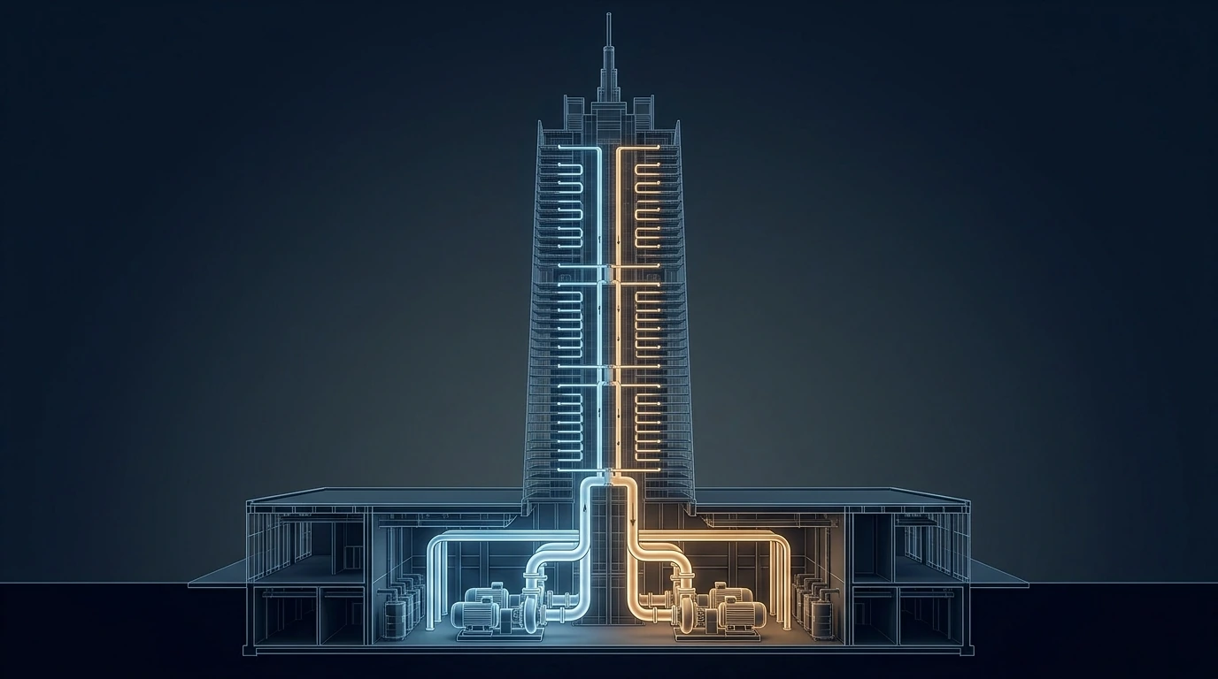
Ask an engineer to size the chilled-water pump for a 600 m tower and you will very often get a number with 600 somewhere in it. That answer is wrong by a factor of fifteen — and the mistake is expensive in both directions, because the same engineer who over-sizes the pump usually under-rates the pipe. In a closed chilled-water loop the water that goes up comes back down, and the returning column pays back every metre the rising column cost: the pump feels friction only. The equipment, meanwhile, feels the entire 59 bar static column and does not care that the loop is closed. Getting those two facts the right way round is the whole foundation of chilled-water design in a tall building, and almost every other decision — zoning, heat exchangers, pump architecture, valve selection, control — is downstream of it.
1 · Why megatall chilled water is a different problem
A chilled-water system in a 10-storey building is a sizing exercise. In a 600 m tower it is a set of interlocking constraints where solving one worsens another:
- Pressure, not flow, sets the architecture. A 600 m water column is 58.9 bar (854 psi) at the base. Ordinary chilled-water fittings, coils, control valves and flanges are PN16 (16 bar); high-pressure lines reach PN25 or PN40. You cannot run one loop top to bottom, so the tower is divided into vertical pressure zones — and every zone break is a decision that costs either money or temperature.
- Every zone break costs you cold. The usual way to break pressure is a plate heat exchanger, and a heat exchanger cannot transfer heat without a temperature difference. Each one pushes the plant's supply temperature down by its approach, and colder supply means a less efficient chiller for the entire building, all year.
- The differential pressure across a terminal varies enormously with height. A two-port control valve on level 5 of a zone sees a completely different ΔP from the identical valve on level 45. Ordinary valves lose authority and hunt; this is why tall buildings and pressure-independent valves belong together.
- The risers move. A 600 m steel riser going from erection temperature to operating temperature changes length by about 144 mm, and the concrete core it is fixed to shortens over years by a comparable amount through creep and shrinkage. Anchors, guides and expansion devices are structural design, not pipe fitting.
- Part-load is the whole life of the plant. A tower spends almost none of its hours at design flow. The pump you select is a peak-day artefact; the pump you actually pay for is the one running at 40–60 % flow for twenty years, and its energy is decided by a control decision — where you put the differential-pressure sensor — far more than by the pump's catalogue efficiency.
This article is about the pumps. The plant that feeds them — chiller types, staging, part-load efficiency and the low-ΔT syndrome — is covered in chiller plant design, and the two are best read together.
2 · What the pump actually sees: the closed-loop truth
In an open system — a fire standpipe, a domestic-water booster, a transfer pump to a roof tank — the pump must lift the water and the lift is real work. That is the physics behind pressure zoning of fire standpipes. A chilled-water loop is closed: the supply riser goes up, the return riser comes down, and the two columns are connected. The weight of water in the down-leg pushes the pump exactly as hard as the weight in the up-leg resists it. Net static head is zero, at any height[1][2]:
The consequence is counter-intuitive and worth stating bluntly: a taller tower needs a bigger pump only because the pipe is longer, not because the building is high. Doubling the height roughly doubles the riser friction, which is a fraction of the total head — it does not double the head, and it certainly does not add 300 m to it.
What does scale directly with height is the static pressure the system must contain. At the lowest point of a zone, the pipe, flanges, valves, coil headers, strainer bodies, pump casings and gaskets all carry the full weight of the water above them, whether the pump is running or not. That number climbs at 0.0981 bar per metre and it is the number that dictates the architecture.
3 · Interactive: pump head vs static pressure
Set the load the riser carries, the design ΔT, the velocity you are willing to run the riser at, and the losses in everything that is not riser. The blue curve is the head the pump actually has to produce; the red line is the static pressure the equipment at the base of that column has to withstand. They are plotted in the same units, on the same axes, so the gap between them is the whole point. Watch the ratio in the readout as you take the tower higher.
A 20 MW riser pair at ΔT = 8 K carries 597 L/s in a DN500 riser and needs about 39 m of pump head — roughly 19 m of it riser friction, at 119 Pa/m, over 1,560 m of equivalent pipe. The static pressure at the base of that same column is 600 m, or 58.9 bar. The pump is 15× smaller than the pressure class. Note also how flat the blue curve is: taking the tower from 300 m to 1,000 m raises the pump head from 29 m to 51 m — a 75 % increase in pump head for a 233 % increase in height — while the red line grows in exact proportion. Height is a containment problem, not a pumping problem.
4 · Sizing the flow: ΔT is the most expensive number you will choose
Flow follows from the load and the temperature difference, and nothing else[1][5]:
Because friction rises with roughly the square of flow and pump power with the cube, ΔT propagates through the entire design with enormous leverage. The same 20 MW at ΔT = 5.5 K instead of 8 K needs 868 L/s instead of 597 — 45 % more water, a larger riser through the whole core, larger pumps, larger valves, and a permanent energy penalty. In a tall building the pipe is also very long and buried in a core that will never be modified, so the ΔT decision is effectively irreversible on day one.
Design tall buildings at a wide ΔT — 8 K or more, and then defend it:
- Select coils for the wide ΔT, with enough rows and the right circuiting. A coil selected at 6 K will never deliver 8 K no matter what the schedule says.
- Two-port control valves everywhere — three-port valves guarantee a low ΔT by design, because they blend supply straight into return whenever the coil is not calling.
- No permanent bypasses. Every open bypass, every leaking three-port, every uncontrolled decoupler flow is a direct short from supply to return and pulls the whole system's ΔT down.
- Give the control valve real authority. Valve authority \(\beta = \Delta p_{valve,open} / \Delta p_{branch}\) should be at least 0.25–0.5; below that the valve's characteristic distorts, it controls in the first few percent of travel, hunts, and sits part-open — again degrading ΔT.
The consequences of losing this battle — flow inflation, extra chillers forced online by decoupler backflow, and the pumping penalty — are quantified in the low-ΔT chart in chiller plant design.
5 · Building the head honestly — and where the fat hides
Pump head in a closed loop is a sum of pressure drops along the index circuit: the single hydraulically worst path from pump discharge, out to the most remote terminal, and back. A defensible build-up looks like this, and every line should be a calculation rather than an allowance:
| Component | Typical (m) | Notes |
|---|---|---|
| Supply + return riser friction | 15–30 | The only item that scales with height. Both legs, plus fittings and offsets. |
| Floor mains & branch | 3–8 | To the index terminal and back. |
| Cooling coil | 3–7 | From the selected coil, not a rule of thumb. |
| Control valve (open) | 3–6 | Deliberately generous — this is what buys valve authority. |
| Chiller evaporator | 4–8 | From the chiller selection at the design flow. |
| Plate heat exchanger (per crossing) | 3–6 | Each side. Only where a zone break exists. |
| Strainers, meters, isolation | 2–5 | Clean values; specify the dirty-strainer allowance separately. |
| Safety margin | 0–5 % | See below — this is where designs go wrong. |
6 · Pressure zoning the chilled-water system
Once the static pressure exceeds the rating of ordinary equipment, the tower has to be divided. There are three ways to do it, and real megatall towers use all three in different parts of the building[2][8]:
- Direct, high-pressure equipment. No break: use PN25 or PN40 pipe, valves, coils and fittings for the lower zones. No temperature penalty at all, and hydraulically the simplest system — but the cost lands on every terminal on every floor, and high-pressure coils and control valves in the thousands add up quickly. Practical for one extra zone's worth of height, rarely for four.
- Plate heat exchangers at mechanical floors. The standard solution. Each HX hydraulically separates the zone above from the zone below, so each zone contains only its own static column and can be built in ordinary PN16. The price is a temperature approach at every crossing, plus the pumps, space and maintenance the exchangers bring.
- Gravity/return-side pressure control. Locating plant rooms high in the tower and feeding zones downward changes which end of the zone carries the static and can remove a zone break entirely. This is an architectural decision about where the mechanical floors go, made years before the pump schedule exists.
The cascade trap
How the heat exchangers are arranged matters more than how many there are. In a cascade, zone 1 is fed from the plant, zone 2 from zone 1 through an HX, zone 3 from zone 2 through another, and so on. The approaches add up in series: with four zones and a 1.2 K approach, the top zone is three exchangers away from the plant and the plant must make water 3.6 K colder than the top-floor coils need. In a parallel-fed arrangement, a single high-pressure primary riser — rated for the full column — runs the height of the tower and every zone takes its own HX directly off it. Each zone is then exactly one exchanger from the plant, whatever floor it is on.
The trade is explicit: the parallel scheme needs one expensive high-pressure riser pair, but that is a few hundred metres of heavy pipe in a shaft. The cascade scheme avoids it and pays instead with plant supply temperature — forever, on every chiller, in every operating hour.
7 · Interactive: zoning, the heat-exchanger cascade & the plant temperature penalty
Set the equipment pressure class you intend to build the zones from, the approach of the plate exchangers, and the supply temperature the coils actually need. The chart shows the chilled-water temperature the central plant must produce, against tower height, for both arrangements. The staircases are the zone boundaries. Watch the cascade curve fall through the practical limit for plain water.
At 600 m in PN16 the tower needs four zones. Cascaded, the plant must deliver 3.1 °C — below the ~3.3 °C practical floor for plain water, so the design does not merely cost energy, it fails, and you are pushed into glycol (worse heat transfer, more pumping, more cost) or into re-arranging the zones. Feed the same four zones in parallel from one high-pressure primary and the plant makes 5.5 °C, one approach below the coils, with a chiller penalty of about 3 % instead of 9 %. Raise the class to PN40 and the two schemes converge, because two zones need only one exchanger either way — which is the real argument for high-pressure equipment in the lower half of a tower.
8 · Pump architectures for tall buildings
- Constant primary. Fixed-speed pumps, three-port control at the terminals. Simple, robust, and energy-illiterate: full pump power at every load and a guaranteed low ΔT. Acceptable only for the chiller evaporator circuit in some plants, never for distribution in a tall building.
- Primary–secondary (decoupled). Constant-flow primary pumps dedicated to the chillers, variable-speed secondary pumps serving the distribution, joined by a decoupler (common pipe). Very robust chiller protection and the traditional default. The decoupler must be short, generously sized and correctly located, and the flow in it must be measured — reverse flow in the decoupler is the single clearest diagnostic that the plant is in low-ΔT trouble, because it means the secondary is drawing more flow than the running chillers produce and mixing warm return into the supply.
- Variable primary flow (VPF). One set of variable-speed pumps through the chillers and out to the system, with a minimum-flow bypass valve to protect the evaporators. Fewer pumps, less space, less energy — but it demands chillers that tolerate variable evaporator flow, a fast and well-tuned bypass, and rate-of-change limits on flow. In a tall building the space and pump-room savings are substantial.
- Zone-tertiary pumping. The natural fit for a zoned tower: primary at the plant, secondary distributing to the zone heat exchangers, and a tertiary set on each zone's own loop. Each zone's pumps are then sized for that zone's friction only — small heads, modest powers, and the ability to run each zone on its own schedule.
- Distributed pumping. Removing the central secondary entirely and letting each zone or riser pump draw for itself. Best theoretical energy — no central pump forcing pressure through valves that are throttling it away — but the control is genuinely harder and it needs careful pressure management to avoid one zone starving another.
- Series pumping. Two pumps in series to reach a head one cannot. In a closed loop this is rarely needed for the reason established in section 2; if a chilled-water pump schedule shows series pumping to "reach the top", the head calculation is almost certainly wrong.
9 · Selecting the actual pump
Sizing gives you a duty point. Selection is choosing the machine that will sit on it for twenty years[3][6]:
- Land near BEP, and stay inside the POR. The Hydraulic Institute defines a Preferred Operating Region of roughly 70–120 % of best-efficiency flow; outside it, radial loads, vibration and recirculation shorten seal and bearing life regardless of what the efficiency curve says. Select so the design point is at or slightly left of BEP, so that real-world flows — which are almost always lower than design — fall into the POR rather than off the bottom of it.
- Watch the curve shape for parallel duty. Pumps intended to run in parallel need a continuously rising head as flow falls. A flat curve means small head differences cause large flow differences: the pumps share load unequally, one can be pushed back to near shut-off, and the set hunts. Check the combined curve against the system curve, and confirm that a single pump running alone does not run out past its POR — the classic parallel-pump trap covered in parallel and series pump operation.
- Size the motor non-overloading. The motor should cover the whole curve to run-out, not just the duty point, because that is where a pump ends up when a system is not yet balanced or a valve fails open.
- Leave impeller room. Select a casing that will accept a larger impeller, and fit the calculated one. That is how you carry margin without paying for it every hour.
- Verify the ΔT the pump implies. Multiply the selected flow by 4.187 and the design ΔT: if the answer is not the load, something in the chain — coil, chiller or schedule — disagrees with something else. This one-line check catches a surprising number of coordination errors.
10 · NPSH, pressurization & the point of no pressure change
A closed loop has no suction lift, so NPSH is rarely the binding constraint — but tall buildings introduce a related failure that is far more common and much more damaging: the top of the loop going sub-atmospheric[1][6].
- Set the fill pressure from the highest point, not the plant. The cold-fill pressure at the pressurisation unit must keep every point in the circuit above atmospheric with margin — the static height of the highest point above the unit, plus roughly 0.3–0.5 bar. A zone whose top is 90 m above its plant room needs about 9.3 bar of cold fill at the base. Get this wrong and the top of the riser sits under vacuum, drawing air in through every vent and gland.
- Connect the expansion vessel at the pump suction — always. The point where the expansion vessel joins the system is the point of no pressure change: the pump cannot alter the pressure there. Connect it at the suction and the pump adds its head to the rest of the system, pushing pressure up everywhere. Connect it at the discharge and the pump subtracts its head from the system — and in a tall riser that is exactly how you pull the top of the loop below atmospheric the moment the pump starts. It is a single tee position on a drawing and it decides whether the system breathes air for its whole life.
- Air separation belongs where air comes out of solution — the point of highest temperature and lowest pressure, which in a chilled-water tower means the top of the risers. Automatic air vents at every high point, a proper de-aerator on the plant side, and a commissioning fill procedure that vents systematically from the bottom up.
- Protect against transients. Long, heavy risers with fast-acting valves and check valves make a chilled-water system capable of real water hammer. Slow-closing valves, correct check-valve selection, and surge analysis where the risers are long enough to warrant it — the same discipline as valve closure and water hammer.
11 · Interactive: DP sensor location and the real part-load curve
The affinity laws promise that half the flow costs one-eighth the power. That is true only if the system curve passes through the origin — pure friction, no fixed head. Real variable-flow systems hold a differential-pressure setpoint somewhere, and where you measure it decides how much of the cube law you actually get. Set the part-load flow and drag the setpoint from "sensor at the pump" (the whole design head held at all times) down towards "sensor at the index terminal" and beyond, to DP reset. The pump curve slides down under the affinity laws; the operating point walks along the control curve; the power readout is where the money is.
At 50 % flow the three strategies are not close. Sensor at the pump: the control curve is flat, the pump barely slows (94 % speed) and draws 50 % of design power. Sensor at the index terminal (β ≈ 0.3): 66 % speed and 23.8 %. Ideal DP reset (β → 0): 50 % speed and 12.5 %, the textbook cube. That is a 4:1 spread in running power from a decision about where to mount a sensor and how to write a reset sequence — no different pump, no different pipe. In a tall building, run the sensor to the hydraulically most remote terminal of each zone, then reset the setpoint down until the most-open control valve in that zone is nearly wide open. This is the highest-return control sequence in the whole chilled-water system.
12 · Getting the variable-speed drive right
- Respect a minimum speed. Typically 25–30 Hz. Below it, mechanical seal faces lose their lubricating film and thrust balance degrades — and the energy saving from going lower is negligible anyway because the curve is already flat there.
- Stage on efficiency, not on flow alone. With variable-speed pumps in parallel, two pumps at half speed are usually more efficient than one at full speed. Base the staging on total power, with hysteresis and minimum run times so the set does not chatter around the changeover.
- Never let the VFD substitute for a wrong impeller. A pump permanently running at 70 % speed because it was oversized is a pump with the wrong impeller. Trim it. The drive should absorb load variation, not a design error.
- Handle the electrical side deliberately. Long motor cables in a tall building cause reflected-wave voltage doubling at the motor terminals — specify inverter-duty motors, dV/dt or sine filters where cable runs are long, and shaft-grounding rings or insulated non-drive-end bearings to prevent bearing fluting from common-mode currents. This is a routine and expensive failure in tall buildings and it is entirely preventable at specification.
- Check harmonics at the system level. Many large drives on one substation is a distortion problem; specify the limits and the mitigation (line reactors, 18-pulse or active front ends) as a package, not drive by drive.
13 · Installation & execution tricks
- Give the suction a straight run. Five to ten diameters of straight pipe into the suction flange. Where a suction diffuser is unavoidable, treat it as a compromise and not as a licence to elbow straight onto the pump.
- Eccentric reducer, flat side up. On a horizontal suction this is the difference between a clean approach and a permanent air pocket sitting at the impeller eye.
- Refuse triple-duty valves. Combining check, isolation and balancing in one body gives poor flow measurement, high loss and a component you cannot service or verify. Separate check valve, separate isolation, separate balancing device with proper pressure tappings.
- Check pipe strain, and prove it. Loosen the flange bolts with the system full and measure movement with a dial gauge. If the pipe pulls the casing, the alignment you signed off is fiction. Then do the final laser alignment after grouting and after the pipework is connected, not before.
- Inertia bases and isolators. Concrete inertia bases of roughly 1.5–2× pump mass on spring isolators, with flexible connectors on both sides — and flexible connectors are for vibration, never for correcting misalignment.
- Anchor and guide the risers as a structural problem. With about 144 mm of thermal movement over 600 m, plus long-term shortening of the concrete core through creep and shrinkage, riser anchors, guides, expansion loops or bellows and slab-penetration details must be engineered and the loads given to the structural engineer. This is the item most often left to the installer, and the one most likely to tear a riser.
- Flush properly, then remove the start-up screens. Fine start-up strainer screens are for commissioning; left in, they collapse into the pump. Log their removal as a formal hold point with a signature against each pump.
- Fit the instrumentation that lets you prove the pump. Pressure tappings either side of every pump, a permanent flow meter on each circuit, and power monitoring on each drive. Then field-verify the pump curve at commissioning — measure head and flow, plot the real operating point and compare it with the selection. Nameplate agreement is not verification.
- Commission the control, not just the hardware. Balance with the control valves driven open, set the DP setpoint from the actual index terminal, then commission the DP reset sequence and record the resulting setpoint against load. A perfectly installed pump on a badly commissioned setpoint delivers the 50 % power case from chart 3.
- Rotate the standby. Automatic duty rotation on a weekly cycle, so the standby pump is proven and its seals do not dry out — and so both machines age evenly.
14 · The design & installation checklist
- Separate the two pressures — pump head from friction on the index circuit; equipment rating from the full static column. Never let one contaminate the other.
- Choose a wide ΔT and defend it — coils selected for it, two-port valves, no bypasses, valve authority ≥ 0.25–0.5.
- Calculate the head, do not pad it — margin goes in the impeller size, not the duty point.
- Zone for pressure, then choose the topology — parallel-fed heat exchangers off a high-pressure primary wherever the cascade penalty would depress plant supply temperature significantly.
- Check the plant temperature is achievable — cascaded approaches can drive the requirement below the practical limit for plain water before anyone notices.
- Pick the architecture for the zoning — primary/secondary/zone-tertiary or VPF; measure the decoupler flow and alarm on reverse flow.
- Select at BEP, inside the POR, with a rising curve for parallel duty and a non-overloading motor.
- Set fill pressure from the highest point and put the expansion vessel on the pump suction.
- Use pressure-independent control valves where the ΔP varies widely up a zone — which in a tall building is everywhere.
- Put the DP sensor at the index terminal and commission a reset sequence — this is worth more than any equipment upgrade.
- Engineer the riser supports for thermal movement and structural shortening, with the loads issued to the structural engineer.
- Prove it on site — pipe-strain check, post-grout laser alignment, start-up screens removed and signed off, field-verified pump curves, and a commissioned control sequence.
References & standards
- ASHRAE Handbook — HVAC Systems and Equipment, Ch. 13 Hydronic Heating and Cooling and Ch. 44 Centrifugal Pumps (closed-loop head, expansion tank location and the point of no pressure change, system pressurization).
- ASHRAE Design Guide for Tall, Supertall, and Megatall Building Systems, 2nd ed. — vertical pressure zoning, heat-exchanger interfaces, riser design and plant location in tall buildings.
- Hydraulic Institute — ANSI/HI 9.6.3 Rotodynamic Pumps: Guideline for Operating Regions (BEP, Preferred and Allowable Operating Regions) and ANSI/HI 9.6.1 NPSH Margin.
- ANSI/ASHRAE/IES Standard 90.1 — Energy Standard for Buildings: variable-flow hydronic requirements, pump power limits and differential-pressure reset.
- Taylor, S.T. Degrading Chilled Water Plant Delta-T: Causes and Mitigation, ASHRAE Transactions; and Primary-Only vs. Primary-Secondary Variable Flow Systems, ASHRAE Journal.
- Rishel, J.B. HVAC Pump Handbook / Water Pumps and Pumping Systems, McGraw-Hill — variable-speed pumping, DP sensor location and control curves.
- Hydraulic Institute & Europump, Variable Speed Pumping: A Guide to Successful Applications; and ASHRAE Fundamentals, Ch. 22 Pipe Sizing (Darcy–Weisbach, friction factors).
- CIBSE Guide B and Guide H; CIBSE Commissioning Code W — Water Distribution Systems; and BSRIA guidance on pre-commission cleaning and hydronic balancing.