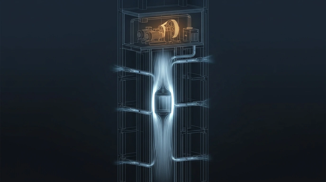
The lifts are somebody else's package. The vertical transportation consultant sizes them, a specialist contractor installs them, and the mechanical engineer's name appears nowhere on the drawings. Yet the lift installation is simultaneously the tower's largest concentrated heat source outside the plant rooms, its dominant chimney, a piston that generates hundreds of pascals every time a car moves at speed, and — in a fire — a protected escape route that only works if a pressurisation system nobody has coordinated is holding the right pressure across doors that are already fighting the stack effect. Almost every one of those is an MEP responsibility, and almost every one is discovered late.
1 · The four interfaces that matter
- Heat. Machine rooms and machine-room-less (MRL) drive cabinets reject the losses of very large motors. A bank of eight high-rise lifts can dump over 100 kW into a small room at the top of a zone — a room that is often unconditioned in the concept design because nobody asked.
- Air. The hoistway is the tallest, smoothest, warmest shaft in the building and therefore the principal path for stack effect. Whether it is vented, sealed or pressurised is an MEP decision with consequences for the whole tower.
- Pressure transients. A car moving at 10 m/s in a close-fitting shaft is a piston. The pressure it generates ahead of and behind it can reach 160 Pa or more, and it lands on top of the stack pressure that is already there.
- Fire. Fire-service and occupant-evacuation lifts require pressurised, protected shafts and lobbies with guaranteed power — the life-safety half of the problem covered in firefighting in megatall buildings.
2 · Machine room heat — the load nobody scheduled
A lift motor does not consume its rated power continuously; it draws heavily on acceleration and up-travel, regenerates on down-travel with a full car, and idles between trips. The heat rejected into the machine space is the system loss multiplied by the duty:
with \(\eta_{sys}\) the combined motor, drive and gear efficiency and \(f_{duty}\) the fraction of time under load through the design hour. For eight lifts of 150 kW at 80 % system efficiency and a 45 % duty that is 108 kW into one room. Three consequences follow immediately:
- It needs mechanical cooling, not ventilation. Lift equipment is typically limited to about 35–40 °C ambient, and drives derate or trip above it. Outside-air ventilation cannot hold that in a Gulf summer, so the machine room needs a dedicated cooling system on essential power.
- It must not fail. If the machine-room cooling trips, the lifts trip — which in a megatall building is an evacuation problem, not a comfort complaint. N+1 cooling and essential-power supply are proportionate.
- Regenerative drives change the number. Drives that return energy to the building rather than burning it in a resistor bank cut both the room's heat load and the tower's energy bill; the trade is harmonic distortion and a grid connection that will accept export.
Eight 150 kW machines produce 108 kW — about 31 tons of cooling in a room the size of a large apartment, on the highest occupied level of a zone where getting chilled water to it is least convenient. Trying to remove it with outside air needs 11 m³/s at an 8 K rise, which in a 45 °C ambient does not produce a 35 °C room at all. Add regenerative drives at 30 % recovery and the room load drops to about 76 kW while the recovered energy goes back into the building. The number to take away is that this room is a plant room with a chilled-water requirement, not a cupboard with a wall fan.
3 · Piston effect — the transient nobody models
A lift car nearly fills its shaft. When it moves, the air ahead must escape through the annular gap around the car and through door leakage, and the resulting pressure is roughly[3]:
The blockage ratio is what makes this severe. At 60 % blockage a car at 10 m/s drives air through the annulus at 15 m/s and generates around 160 Pa; tighten the shaft to 75 % blockage and the same car produces over 600 Pa. This pressure is transient and additive — it arrives on top of the stack pressure already across the landing doors, and it is the reason lift doors on the low floors of a tall zone in winter misbehave intermittently rather than consistently.
- Give the shaft free area. Blockage ratio is the dominant variable, and it is fixed by the architect and the lift consultant when the shaft is dimensioned. A slightly larger shaft is enormously cheaper than the noise and door problems it prevents.
- Vent between shafts, not to the building. Inter-shaft openings within a lift bank let the air displaced by a rising car be taken by the shaft of a descending one, cancelling much of the pressure. This is very effective and it is a coordination item, not a product.
- Aerodynamic car shrouds on the fastest lifts reduce both the pressure and the noise; above about 7 m/s they are standard on serious installations.
- Do not solve it with a permanent shaft vent. That fixes the piston effect and dramatically worsens the stack effect, as set out in stack effect — it drags the neutral plane to the roof and lands the whole stack pressure on the entrance lobby.
A 10 m/s car at 60 % blockage produces 162 Pa, comfortably past the point where landing doors bind — and that is before any stack pressure is added. Hold the same speed and open the shaft out to 48 % blockage and the pressure falls inside tolerance. The chart's real message is the exponent: pressure goes as the square of both speed and the blockage function, so the shaft dimension chosen in the concept design is worth far more than anything the MEP engineer can add later.
4 · Hoistway and lobby pressurisation
Fire-service lifts, occupant-evacuation lifts and, increasingly, all lifts in a tall building require the shaft or its lobby to be held at positive pressure so smoke cannot enter. The airflow follows from the leakage area and the pressure to be held:
A hoistway is leaky: every landing door is a large gap, and there are as many of them as there are floors. One square metre of effective leakage area at 50 Pa needs about 9 m³/s — a substantial fan and a substantial shaft to feed it. The design difficulties are the same ones the stack-effect article sets out, sharpened:
- The pressure budget is tiny. The system must hold enough pressure to exclude smoke, but landing doors and adjacent stair doors must still work; the stack effect has usually spent most of the allowance before the fan starts.
- Inject at multiple levels. A single injection point at the top or bottom of a 600 m shaft cannot produce a uniform profile against the shaft's own stack gradient.
- Relieve the doors-closed case. With every door shut, a fan sized for the doors-open case will over-pressurise; barometric or modulating relief is required.
- Pressurise the lobby as an alternative. Pressurising protected lobbies rather than the shafts is often easier to control, uses less air, and puts the pressure where the smoke barrier actually is.
Sixty landing doors at 0.02 m² each give 1.2 m² of leakage and need 7.0 m³/s just to hold 50 Pa with everything shut — rising to 30.5 m³/s if the same 50 Pa has to be held with two doors open. That 4.3:1 turndown between the two design cases is the whole control problem: a fan big enough for the open-door case will destroy the closed-door case unless relief or variable speed is provided, and a fan sized for the closed-door case simply fails when the fire service opens a door. One caveat that decides how much air you actually buy: the codes do not require full pressure to be held with a door open. EN 12101-6 and NFPA 92 set the open-door case as a velocity through the opening — typically 0.75–2 m/s — which is a fraction of the air needed to hold 50 Pa. Establish with the authority which criterion applies before selecting the fan, then specify and commission both cases explicitly.
5 · Installation, coordination & execution tricks
- Get the machine-room cooling into the concept design. The single most common failure on this interface is a lift machine room with no chilled water route, discovered when the risers are already cast. Put it on the zone schematic at concept stage with its load, its N+1 requirement and its essential-power supply.
- Never route anything else through a hoistway. Codes prohibit it and it is still attempted — no pipework, no cabling, no drainage other than what serves the lift itself.
- Drain the pit, and think about where the water comes from. Pits flood from sprinkler discharge, washdown and groundwater. Provide a drained, pumped pit with an oil separator, and coordinate the sprinkler and shunt-trip arrangement so power is isolated before water is discharged into a shaft with live equipment.
- Fire-stop the landing door surrounds and the shaft penetrations to the rated standard — they are both a fire barrier and the leakage area in the pressurisation calculation, so a poor installation fails twice.
- Coordinate the shunt trip, the fire alarm and the lift controller as one sequence, and test it as one sequence. Phase 1 recall, Phase 2 fire-service operation, machine-room cooling status and pressurisation start-up all interact.
- Measure the real door differential at commissioning, at the top and bottom of every zone, with the pressurisation running and with it off, and in the design season. The stack article's recommendation for permanent differential-pressure sensors applies here more than anywhere.
- Check harmonics from the drives. A bank of large regenerative drives is a significant harmonic source close to sensitive equipment; specify the limits and the mitigation with the electrical engineer rather than accepting the lift supplier's default.
- Plan the rope and machine replacement route at the machine room, with a certified lifting beam — the same discipline as any other plant room.
6 · The design & installation checklist
- Schedule the machine-room heat load per group, with cooling on essential power and N+1 where lift availability is critical.
- Evaluate regenerative drives for both room load and building energy, with the harmonic consequence priced.
- Fix the shaft blockage ratio early — it is the dominant piston-effect variable and it belongs in the concept dialogue with the VT consultant.
- Provide inter-shaft venting within lift banks rather than venting shafts to atmosphere.
- Design pressurisation for both the doors-open and doors-closed cases, with multi-level injection and relief.
- Do not vent hoistways permanently — coordinate with the stack-effect strategy.
- Drain and protect the pit, and coordinate sprinkler discharge with power isolation.
- Fire-stop landing surrounds to both the fire rating and the assumed leakage area.
- Test the whole fire sequence end to end, and measure real door differentials in season.
References & standards
- CIBSE Guide D — Transportation Systems in Buildings — lift heat gains, machine room environment, shaft design and interfaces with building services.
- ASHRAE Design Guide for Tall, Supertall, and Megatall Building Systems, 2nd ed. — lift machine room cooling, hoistway pressurisation and stack-effect interaction.
- Klote, J.H. & Milke, J.A. Handbook of Smoke Control Engineering (ASHRAE/SFPE/ICC) — elevator piston effect, hoistway pressurisation and door forces.
- NFPA 92 — Standard for Smoke Control Systems: pressurisation design cases, doors-open criteria and relief requirements; and EN 12101-6 for pressure differential systems.
- EN 81-20 / EN 81-50 and ASME A17.1 — lift safety requirements including machine room environment, pit drainage and firefighter lift provisions.
- ISO 25745 — energy performance of lifts, including regenerative drive assessment and duty categories.
- Council on Tall Buildings and Urban Habitat (CTBUH) — tall building vertical transportation strategy, sky lobbies and lift zoning.
- International Building Code (IBC) and Saudi Building Code SBC 801 — fire-service access lifts, occupant evacuation elevators and hoistway protection.