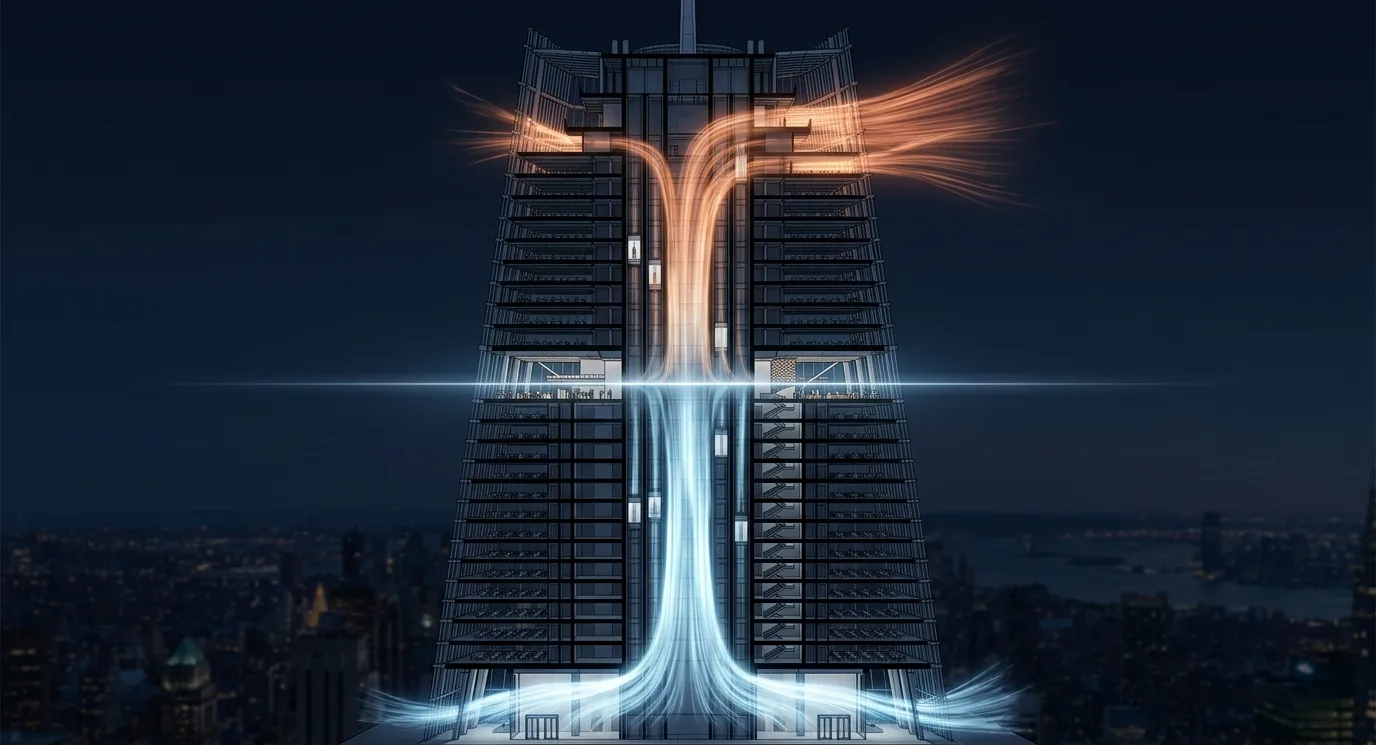
There is a chimney inside your building. Nobody drew it, nobody sized it, and it is the full height of the tower. It pulls outside air in through the lobby doors, drives it up every lift shaft, stair and service riser, and pushes it out through the upper floors — and in a megatall building it does this hard enough to jam a stair door shut, hold a lift door open, make a doorway whistle, carry cooking odours forty floors, move smoke the entire height of the core, and quietly burn megawatts. Stack effect is not an operational nuisance to be solved by the facilities team. It is a design load, as real as wind, and like wind it must be resolved on the drawing board — because almost every effective remedy is architecture and compartmentation, not equipment.
1 · Why stack effect becomes a megatall problem
Stack effect exists in a two-storey house. It matters in a tower for one reason: the driving pressure is directly proportional to height, while every device it acts on — a door leaf, a lift door, a damper, a trap seal — stays exactly the same size. Scale one side of the equation by 100 and leave the other alone, and things that were invisible at 20 m become governing at 600 m.
- The pressure is not small. A 600 m tower at 0 °C outside and 21 °C inside develops roughly 280 Pa between the top of the shaft and the neutral plane. For comparison, a stair-pressurization system is designed to hold about 25–50 Pa. The uncontrolled natural phenomenon is five to ten times stronger than the engineered system meant to manage the same doors.
- It never switches off. Wind is intermittent; stack effect runs every hour that the inside and outside temperatures differ. It is the building's baseline pressure regime, and every other pressure — ventilation, pressurization, lift piston effect, wind — sits on top of it.
- It is a whole-building phenomenon. There is no local fix. The lift-shaft problem on level 3 is caused by the shaft geometry on levels 1 to 100 and by how tight the roof is. You cannot solve it floor by floor.
- It is decided in concrete. The single most powerful control is where the shafts stop — sky lobbies, mechanical floors, lift zoning, lobby vestibules. Those are set by the architect and the vertical-transportation consultant years before an air-balance report exists.
- It cross-couples with fire safety. The same pressure that makes a door hard to open is the pressure that will carry smoke up the core. Smoke control and stack effect are one problem, solved once.[2][4] Firefighting in megatall buildings covers the fire-side half of it.
2 · The physics: driving pressure and the neutral plane
Air is a fluid with weight. A column of warm indoor air is lighter than a column of cold outdoor air of the same height, so the two columns cannot balance at every level — they can only cross at one. The pressure difference between inside and outside, at a height \(h\) measured from that crossing point, is[1][2]:
Two things follow immediately, and both matter more than the number itself:
- The gradient is fixed by temperature alone. At 0 °C outside / 21 °C inside the coefficient works out to about 0.90 Pa per metre of height. At −20 °C it is about 1.9 Pa/m. This gradient is a property of the weather, not of your design. You cannot reduce it.
- The only thing you control is \(h\). \(h\) is not the height of the building — it is the height of the continuous air column being driven, measured from the neutral plane. Break that column and you shrink \(h\). This is the whole design strategy in one sentence, and everything in section 9 follows from it.
Where the neutral plane actually sits
The neutral plane (or neutral pressure level, NPL) is the height at which inside and outside pressure are equal. Below it the building is at negative pressure and sucks air in; above it the building is positive and blows air out. Textbooks say "roughly mid-height", but its real position is set by the distribution of leakage area between the top and bottom of the building. Equating the mass flow in at the bottom to the mass flow out at the top for a winter (upward) stack gives[1][5]:
with \(z\) the NPL height above grade and \(A\) the effective leakage areas. Equal leakage top and bottom puts the NPL at about 0.48 H in winter — just below mid-height. But make the top four times leakier than the bottom and the NPL climbs above 0.9 H; make the top four times tighter and it drops below 0.15 H. That is an enormous swing, and it is the one property of the stack profile a designer can genuinely move.
3 · Interactive: the stack profile & the neutral plane
Set the outdoor and indoor temperatures, the height of the continuous air column, and the ratio of top-to-bottom leakage area. The curve is the pressure difference between the inside of the shaft and outside, up the height of the tower: negative below the neutral plane (air pushed in), zero at it, positive above it (air pushed out). Drag the leakage ratio and watch the neutral plane — and therefore the pressure landing on your lobby doors — slide up and down the tower. Push the outdoor temperature above the indoor temperature and the whole profile inverts: that is the reverse stack of a Gulf summer.
At the default 600 m, 0 °C case the gradient is 0.90 Pa/m and the neutral plane sits at 289 m — so the lobby sees about 261 Pa of suction and the top of the shaft about 281 Pa of push. Now drag the leakage ratio down to 0.4: the neutral plane falls to about 78 m and the lobby load drops to roughly 70 Pa, at the price of ~470 Pa at the top of a shaft that has almost no openings to lose it through. That trade — move the pressure to where there are no doors — is free if you make it in the design, and impossible to make later.
4 · Winter stack, summer reverse stack — and why the Gulf case is different
Almost every stack-effect reference is written for a cold climate, where the inside is warm, the air rises, and the building inhales at the lobby. In the Gulf the sign flips for most of the year, and the consequences flip with it. Run the numbers at real design conditions[1][5]:
| Design case | To (°C) | Ti (°C) | Gradient (Pa/m) | Δp over 300 m (Pa) | Direction |
|---|---|---|---|---|---|
| Severe cold (Chicago, Moscow) | −20 | 21 | 1.91 | 572 | Upward |
| Temperate winter (London, New York) | 0 | 21 | 0.90 | 271 | Upward |
| Riyadh / Jeddah winter | 8 | 22 | 0.58 | 175 | Upward |
| Gulf summer, conditioned core | 45 | 24 | 0.77 | 231 | Downward |
| Gulf summer, extreme day | 50 | 23 | 0.98 | 293 | Downward |
Read the last two rows carefully. A Gulf summer at 45–50 °C outside against a 23–24 °C conditioned core produces a stack effect as strong as a European winter — and it runs in the opposite direction. Air is drawn in at the top of the tower and pushed out at the bottom. Every intuition imported from a cold-climate textbook is now backwards:
- Smoke and odours travel down, not up. A fire in an upper zone can drive smoke down the shafts into the podium and the basement car park. Smoke-control zoning designed only for upward migration misses this entirely.
- The lobby doors are blown open, not sucked shut. Below the neutral plane the building is now positive, so revolving doors run away, swing doors slam outward, and glazed lobby doors take a permanent set. The failure mode is different but the force is the same.
- The infiltration load lands high, not low. Hot, humid outside air is drawn in through the upper façade — exactly where the glass is largest, the wind is strongest and the AHU serving the zone is smallest. Condensation risk moves to the top of the tower.
- Shoulder seasons still bite. A tower that is neutral in March is not a tower with no stack effect — it is a tower whose neutral plane sweeps through the full height twice a year, taking the pressure problem to every floor in turn.
5 · What stack effect actually breaks
The equation is abstract; the defect list is not. Every item below is a routine tall-building complaint whose root cause is the stack pressure, and every one is diagnosed by measuring Δp across the offending door or shaft, not by adjusting the device:
- Doors that will not open — stair doors at the top of the tower and lobby doors at the bottom. The commonest and most serious, because it is a life-safety failure, not a comfort one. Quantified in sections 6 and 7.
- Lift doors that will not close, or reopen repeatedly. A car door is a light, low-friction panel with a wide face. Differential pressure across a landing door of only ~50–75 Pa is enough to bind the door gibs, defeat the door operator's closing force and trip the reopening device — usually at the lowest floors in winter and the highest floors in summer. This is the single most frequent stack-effect complaint in occupied towers.
- Whistling and howling. Air forced through a door undercut or a lift-landing gap at 150–300 Pa reaches high velocity in a narrow slot. The noise is unmistakable, and it is the pressure telling you where the leakage path is.
- Lobby doors and revolving doors that fight the user. Swing doors need two hands; revolving doors either drag or accelerate on their own; automatic sliders re-open on the safety beam because they cannot seal against the pressure.
- Odour, smoke and contaminant migration. Kitchen and toilet exhaust, car-park fumes, cooking odours in residential towers and — critically — fire smoke all ride the shaft. This is the mechanism by which a fire on level 5 puts smoke on level 90.[2][4]
- Ventilation systems that will not balance. The pressure across the AHU outdoor-air and relief dampers varies by hundreds of pascals from the bottom of the tower to the top. Systems balanced in the shoulder season go badly off in January and July, and constant-volume terminals at the extremes of the tower simply lose authority.
- Drainage trap-seal loss. Stack pressure applied across a shallow water seal empties it and lets drainage gases into the occupied floors — a problem shared with the drainage stack's own air regime, covered in drainage and stormwater in tall buildings.
- Condensation and frost. Warm humid indoor air driven out through the upper façade in winter condenses inside the construction; hot humid outdoor air drawn in high in a Gulf summer condenses on cold interior surfaces. Both are stack-driven envelope failures, not vapour-barrier failures.
- Energy. The infiltration this all represents is a continuous, uncontrolled outdoor-air load measured in megawatts on a megatall tower. Quantified in section 11.
6 · Doors — the number that governs life safety
A door is a lever. The pressure acts over the whole leaf, but the occupant pulls at the handle, near the edge, so the moment about the hinge converts the distributed pressure into a very large force at the knob. The standard expression is[2][4]:
where \(F\) is the total force at the knob (N), \(F_{dc}\) the force to overcome the door closer alone (N), \(W\) the door width (m), \(A\) the door area (m²), \(d\) the distance from the knob to the door edge (typically 0.076 m), and \(\Delta p\) the pressure difference across the door (Pa). For a standard 0.91 × 2.13 m leaf this reduces to about 1.06 N of extra force for every 1 Pa across the door.
Codes set the maximum door-opening force in the region of 133 N (30 lbf) for a side-hinged swinging egress door[6]. That single number, run backwards through the equation, is the real design constraint:
With a fairly typical 60 N closer, the answer is about 69 Pa. That is the entire pressure budget available across any egress door in the building — for stack effect, pressurization, wind and HVAC imbalance combined. Against a 600 m column producing 270 Pa, the arithmetic is brutal: the door is roughly four times over its limit before a single fan has been switched on.
7 · Interactive: door force & the compartmentation fix
This is the same building as chart 1, read through a door. The red line is the force needed to open a door onto an undivided full-height shaft, at every level of the tower. The blue line is the same door when the shaft is broken into \(N\) compartments — at sky lobbies, mechanical floors, or simply by lobby doors in front of the lift landing. Each compartment gets its own neutral plane, so the driving height across any one door is \(H/N\). Slide \(N\) up until the blue curve stays left of the 133 N line, and you have just sized the compartmentation strategy for the tower.
The default case — 600 m, 0 °C, one continuous shaft, 60 N closer — needs 347 N to open a stair door at the top of the tower. That is not "stiff"; it is immovable for most adults, and it is the door people are meant to escape through. Break the shaft into four compartments and the worst case falls to about 132 N, right on the limit. Add a lighter 40 N closer and it drops to 112 N with margin to spare for wind and pressurization. Note that the "zones needed" readout assumes stack effect gets the whole budget — in a real design you must leave 25–50 Pa of it for the pressurization system, which pushes the answer up by one or two zones.
8 · Lifts — the shaft that makes the chimney
Of all the vertical paths in a tower, the lift shaft is the one that matters. It is tall, smooth, large in cross-section, warm, and it connects every floor through a landing door that is a deliberately imperfect seal. In most tall buildings the lift shafts carry the majority of the stack airflow, which is why lift problems are the first symptom and lift zoning is the first cure.
- Landing-door pressure is the limiting case. A lift landing door is not an egress door and has no 133 N allowance to hide behind — it simply fails to operate. Practical experience puts the threshold for reliable door operation at roughly 50–75 Pa across the landing door, well below the stair-door limit.
- Lift zoning is compartmentation you are getting anyway. A megatall tower already divides its lifts into local zones served from sky lobbies, because a single shaft cannot serve 150 floors economically. Each zone's shafts terminate at a sky lobby. If — and only if — those sky lobbies are properly separated from each other by lobby doors and floor-slab sealing, the vertical transportation strategy has already delivered the compartmentation the air needs. Design the two together: the lift zoning diagram and the stack-effect strategy are the same drawing.
- Shaft vents are chimney flues. Historic codes required a permanent vent of a few percent of shaft area at the top of every hoistway. That vent is an ideal top-of-building opening: it drags the neutral plane to the roof and puts the entire stack pressure onto the lobby. Modern codes permit — and good design demands — that the vent be omitted or motorised and normally closed in sprinklered towers, with the shaft instead protected by hoistway pressurization and smoke detection. Eliminating a permanent open shaft vent is one of the highest-value stack-effect decisions available, and it is a code-negotiation item, not an equipment item.
- Lift-lobby doors are the cheapest vestibule in the building. Putting a door between the lift landing and the office floor turns one leaky seal into two in series. It halves the pressure across each leaf, cuts the leakage flow by roughly 30 % for equal-area seals, and — in the lower third of a tower in winter — is often the difference between doors that work and doors that do not.
- Piston effect is a separate, additive problem. A 10 m/s car in a close-fitting shaft generates its own transient pressure pulse of the order of tens of pascals ahead of and behind it. It does not cause the stack effect, but it lands on top of it and can push a marginal door over the threshold. Shaft cross-section, car-to-shaft clearance and inter-shaft venting are the levers.
9 · The design toolbox, part 1 — break the column
Everything effective comes back to the same term in the same equation: reduce \(h\), the height of the continuous air column. In rough order of power per unit of cost:
- Terminate the shafts. Lift zoning with sky lobbies, stair transfers at mechanical floors, and service risers that stop and restart at plant levels. Three 200 m columns instead of one 600 m column reduce every pressure by a factor of three. Nothing else comes close.
- Seal the floor-slab plane. A compartment only exists if the air cannot go around it. Every slab penetration — risers, cable trays, ducts, plumbing sleeves, the curtain-wall perimeter joint at every slab edge — is a hole in the compartment. The perimeter slab-edge seal is the most commonly missed vertical leakage path in a curtain-walled tower, and it is a fire-stopping item that is also an air-sealing item; specify it as both and inspect it as both.
- Vestibules and airlocks at the extremes. Two doors in series at the main entrance, at sky lobbies, and at the top-of-stair discharge. Series leakage paths share the pressure: for two comparable leaks the Δp across each leaf roughly halves. Combine with a revolving door at grade — which never presents a fully open path — and the entrance ceases to be the building's main air intake.
- Airlock the basement and the loading dock. In winter these are the biggest low-level openings in the building and they are almost always specified for vehicle logistics with no pressure requirement at all. A single roller shutter left open at the dock can dominate \(A_{bottom}\) for the whole tower. Interlocked double shutters, fast-acting doors and a dedicated dock ventilation strategy are the fix.
- Compartment the chutes. Refuse and linen chutes are unbroken full-height flues with a self-closing door on every floor. Gasket the hopper doors, interlock them, and terminate and pressurise the chute properly — an ungasketed chute is a 600 m open pipe.
- Stair enclosures: continuous but compartmented. Egress stairs must run the full height, so the column cannot simply be cut — but a scissor or transfer arrangement at refuge/mechanical floors, with the stair doorway offset and a vestibule at the transfer, breaks the straight air path without breaking the escape route.
10 · The design toolbox, part 2 — the envelope, the entrance, and moving the neutral plane
- Airtightness is a stack-effect measure, not just an energy measure. The whole-building leakage rate — typically specified at ≤2.0 L/s·m² at 75 Pa by ASHRAE 90.1, with good curtain-wall towers achieving well under 1.0[7] — sets the magnitude of every flow the stack drives. Halve the leakage and you halve the airflow, the energy and the noise, though not the pressure.
- Distribute the tightness deliberately. This is the neutral-plane lever from section 2. Make the top of the building as tight as you can afford — no permanent shaft vents, sealed roof plant rooms, gasketed roof hatches, motorised smoke vents held closed — and accept more leakage low down. The neutral plane drops, the entrance pressure falls, and the residual pressure ends up at the top of the shafts where there is nothing much for it to break. Doing the reverse — a superbly sealed podium under an open shaft head — is the classic own goal.
- Revolving doors, always, at grade. A revolving door maintains a closed air path at every point in its rotation and cuts entrance infiltration by around 80 % compared with a swing door in the same opening. Provide the code-required swing doors alongside, but design the traffic to use the revolving doors and keep the swing leaves on hold-closed hardware.
- Bias the pressure with the ventilation system. The AHUs are a pressure source you already own. Supplying deliberate excess outdoor air to the lower zones — and correspondingly relieving from the upper zones in winter — pushes back against the stack profile and shifts the effective neutral plane. It costs conditioning energy, so it is a trim, not a primary strategy, but it is the one adjustment available after the building is built.
- Give the stack somewhere harmless to go. Where the pressure cannot be eliminated, provide a controlled, silenced, dampered relief path in the shaft head rather than letting the building find its own path through door gaps. A motorised relief damper that opens on a measured differential is far better than a permanent hole.
- Power-assist the doors that remain hard. Automatic operators on the ground-floor and top-floor stair doors are a legitimate final measure — but only after the compartmentation is right, and never as a substitute for it, because a powered door with no power is worse than a heavy door.
11 · Interactive: the energy penalty
Stack effect is usually argued as a comfort and safety problem, which is why it loses to budget. Put it in kilowatts and the conversation changes. This chart integrates the stack-driven infiltration over the façade of the tower and converts it to a heating or cooling load — for a fully connected building, and for the same building compartmented into \(N\) sections. The leakage law is \(q = q_{75}(\Delta p / 75)^{0.65}\), the standard building-envelope power law[1][7].
A 600 m tower with a code-typical 1.5 L/s·m² envelope and no vertical compartmentation carries about 3.1 MW of stack-driven infiltration load at a 0 °C design day — an uncontrolled outdoor-air load that appears in no schedule and is served by no AHU. Tighten the envelope to 0.75 and compartment the shafts into four, and it falls to roughly 0.63 MW: a five-fold reduction, almost all of it bought with sealing details and a lift-zoning diagram rather than plant. Note also the shape of the red curve — because the flow area grows with height and the pressure grows with height, the load rises as roughly \(H^{1.65}\). Stack effect does not scale linearly with your building; it scales worse.
12 · Pressurization designed against the stack profile
Stair and lift-lobby pressurization is where stack effect and fire safety collide, and it is the hardest system in a tall building to make work, because it must satisfy two contradictory requirements simultaneously across a 600 m column[2][3][4]:
- Enough pressure to keep smoke out — typically a minimum of 12.5 Pa in a sprinklered building or 25 Pa unsprinklered under NFPA 92, and about 50 Pa under EN 12101-6 for a Class B system, measured with the doors closed.
- Little enough pressure that the doors still open — the ~69 Pa total budget from section 6, of which the stack effect has usually already taken most.
The gap between those two numbers is the entire design space, and on an uncompartmented megatall shaft the gap is negative — the system is impossible before it is designed. That is the real reason compartmentation is not optional: it is what creates the pressure budget the smoke-control system needs to exist in. Within a properly compartmented tower, the design moves that make pressurization achievable are:
- Multiple injection points — supply the stair at many levels (commonly every 2–4 floors, or at minimum every zone), never from a single fan at one end, so the pressure profile inside the stair follows the profile outside it instead of fighting it.
- Variable-speed fans on measured differential, with the control set-point scheduled against outdoor temperature — including its sign, so the system behaves correctly in a reverse stack.
- Barometric or motorised relief dampers sized for the doors-closed case, so the system does not over-pressurise when every door is shut.
- Design for the doors-open condition explicitly. The code case is typically a defined number of doors open simultaneously; the fan must hold the minimum pressure then, and not exceed the door-force limit when they close.
- Pressurise the lift shafts and lobbies as a system with the stairs, not independently — otherwise each one becomes the other's leakage path and the two systems chase each other.
13 · Installation, commissioning & execution tricks
Stack effect is unusually punishing on site, because it is the sum of a thousand small leaks and every one of them is somebody else's scope. These are the interventions that actually change the outcome:
- Make the slab-edge seal a witnessed hold point. The curtain-wall perimeter joint at every floor is simultaneously a fire-stop, a smoke seal and the tower's principal vertical air path. Inspect it floor by floor as the façade goes up — it is unreachable and unfixable afterwards.
- Seal risers as you build them, not at the end. Every service penetration should be fire-stopped and air-sealed at the time it is made. Retrofitting seals into a congested riser at handover is how buildings end up with a permanent leak they can never find.
- Blower-door or fan-pressurisation test the compartments, not just the building. A whole-building airtightness number tells you nothing about whether your compartmentation exists. Test the sky-lobby separation and the shaft breaks independently, early, on a mock-up or the first completed zone, while the detail can still be corrected.
- Log differential pressure across the critical doors for a full year. Install permanent Δp sensors at the ground-floor stair door, the top-floor stair door, a mid-tower lift landing and the sky-lobby doors, and trend them against outdoor temperature. This is a trivial addition to the BMS and it converts every future complaint from an argument into a data point.
- Commission at the design extreme, or state that you did not. Pressurization and door forces verified in April are not verified. Where the programme forbids seasonal testing, test at the achievable condition and extrapolate the door force with the stack equation, then re-test in the first design season and hold retention against it.
- Close the shaft head before you close the lobby. During construction the tower is a bare chimney with an open top and an open bottom; the stack effect on a topped-out, unglazed tower is severe enough to be a site safety issue and it will slam doors and injure people. Sequence the temporary closures top-down and brief the site on it.
- Fix the door hardware last, and measure it. Closer force, hinge friction, seal drag and latch geometry are all adjustable at the very end and together are worth 20–30 Pa of budget. Measure the actual opening force with a force gauge at the handle on every critical door — not once per type, but on every door on the critical levels — and record it.
- Write the reverse-stack case into the O&M. Facilities teams inherit a building whose behaviour flips sign twice a year. Tell them which season does what, which doors are affected in each, and what the damper and fan set-points should be in each regime.
14 · The design & installation checklist
- Treat stack effect as a design load — compute the gradient at the true design extremes, in both directions, before the core layout is frozen.
- Break the column — lift zoning and sky lobbies, stair transfers at mechanical floors, service risers terminated at plant levels. This is the primary control; everything else is secondary.
- Make the compartments real — slab-edge seals, riser fire-stopping, gasketed chute doors, sealed sky-lobby separations. A compartment with a hole in it is not a compartment.
- Place the neutral plane on purpose — tighten the top (no permanent shaft vents, sealed roof plant), accept leakage low, and take the pressure off the entrance.
- Vestibule the extremes — revolving doors plus airlocks at grade, airlocked loading dock and basement, lift-lobby doors in the lower zones.
- Spend the door budget consciously — 133 N total, of which the closer takes 40–90 N; leave 25–50 Pa for pressurization and a margin for wind before allocating any to stack.
- Design pressurization into the budget compartmentation created — multi-point injection, variable-speed on measured Δp, relief dampers, doors-open and doors-closed cases both proven.
- Specify airtightness numerically — a whole-building target with a test to prove it, distributed deliberately between top and bottom.
- Prove it on site — witnessed slab-edge seals, compartment pressure tests, force-gauge readings on every critical door, permanent Δp trending, and commissioning at (or extrapolated to) the design season.
References & standards
- ASHRAE Handbook — Fundamentals, Chapter 16, Ventilation and Infiltration (stack-effect pressure, neutral pressure level, envelope leakage and the power-law flow model).
- Klote, J.H. & Milke, J.A. Principles of Smoke Management / Handbook of Smoke Control Engineering (ASHRAE / SFPE / ICC) — stack effect, neutral plane, door-opening force and pressurization design.
- NFPA 92 — Standard for Smoke Control Systems (minimum and maximum pressure differences, doors-open design case, stair and hoistway pressurization).
- Tamura, G.T. & Wilson, A.G. (National Research Council Canada). Building pressures caused by chimney action and mechanical ventilation, ASHRAE Transactions — the foundational measured work on stack effect in tall buildings.
- Jo, J.-H., Lim, J.-H., Song, S.-Y., Yeo, M.-S. & Kim, K.-W. Characteristics of pressure distribution and solution to the problems caused by stack effect in high-rise residential buildings, Building and Environment, 42(1), 2007.
- NFPA 101 Life Safety Code and the International Building Code (IBC) — maximum door-opening force for egress doors (133 N / 30 lbf); high-rise provisions. Saudi Building Code SBC 201 / SBC 801 for regional application.
- ANSI/ASHRAE/IES Standard 90.1 — Energy Standard for Buildings Except Low-Rise Residential Buildings (air-barrier requirements and the whole-building air-leakage limit of 2.0 L/s·m² at 75 Pa); ASTM E779 / E1827 test methods.
- Lovatt, J.E. & Wilson, A.G. Stack effect in tall buildings, ASHRAE Transactions; and EN 12101-6, Smoke and heat control systems — Specification for pressure differential systems.