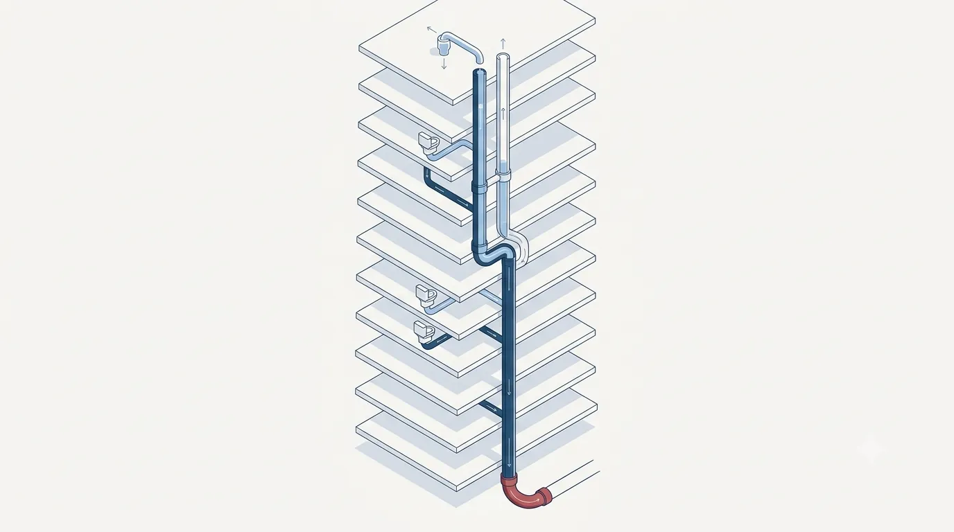
Water supply goes up a tower under pressure you control; drainage comes down under gravity you do not. A single soil stack in a super-tall building can drop waste through 300 metres or more, and what governs its design is not the water at all — it is the air. The falling water drags a column of air with it, and the pressure swings that air creates will empty the water seals in the traps, letting sewer gas into apartments, unless the whole system is engineered to keep those pressures inside a band a few centimetres of water wide. This is the discipline of tall-building drainage: sizing the stacks, managing the air, protecting the seals, turning the offsets, and getting the storm off the roof — all by gravity, with almost no margin for error.
1 · Why tall-building drainage is hard
In a two-storey house the drainage barely matters. In a 60-storey tower it is one of the most failure-prone systems in the building, for reasons that are all consequences of height[1][2]:
- It is one long fall. Waste discharged on floor 55 arrives at the base moving fast and carrying a great deal of entrained air. The energy has to go somewhere.
- The air, not the water, sets the rules. Falling water in the stack behaves like a piston, pulling air down with it. That airflow, meeting the resistance of fittings, the base bend and the below-ground drain, generates suction near the top and back-pressure near the base — the enemy of every trap seal in the building.
- Trap seals are tiny. A typical trap holds only a 50 mm water seal. A pressure transient of a few hundred pascals — a few centimetres of water — is enough to blow it out or siphon it away, and once the seal is gone, sewer gas has a clear path into occupied rooms.
- You cannot repipe a tower. Stacks are cast into the cores and shafts. Getting the sizing, venting and offsets right on the drawing board is the only chance you get.
2 · How a drainage stack really works
The intuition that water "falls faster and faster" down a tall stack is wrong, and the correction is the key to the whole subject. Discharged water does not fill the pipe; it clings to the wall as an annular sheet spiralling down, with a core of air in the middle. Friction with the pipe wall and drag from the air quickly balance gravity, so the sheet reaches a terminal velocity — typically only 3–5 m/s — within a few storeys (the terminal length), and does not accelerate after that no matter how tall the building[2][3]. That single fact is why a 300 m stack is sized almost the same as a 30 m one.
Because the water runs as an annulus, the stack is never designed to run full. It is sized so the water occupies only a fraction of the cross-section — leaving the central air core free to move — and that fraction is the master design variable.
3 · Sizing the stack
Loads are counted in discharge units (DU) or fixture units — each fixture rated by how much and how often it discharges — and the total is converted to a design flow. Codes then set the stack diameter from the flow and the permissible fill. The most physical basis is the Wyly-Eaton equation, which gives the flow a stack can carry at a chosen fraction of cross-section occupied by water[3][4]:
where \(Q\) is in L/s, \(d\) is the stack inside diameter in mm, and \(r_s\) is the ratio of water cross-section to pipe cross-section. Codes cap \(r_s\) at roughly 1/4 to 1/3 (EN 12056 works to a filling degree; the IPC/UPC tabulate the same physics as capacities per diameter). Push \(r_s\) higher to squeeze more flow into a smaller pipe and you choke the air core — the pressure regime becomes violent and the traps go. The next chart is this equation.
4 · Interactive: stack capacity vs diameter & fill
Set the fill ratio and read how much a stack of each diameter can carry. The dashed lines are the code-typical limits (1/4 and 1/3 full); keep your operating point between them. Notice how strongly capacity depends on diameter — it rises with \(d^{8/3}\), so one pipe size up buys a lot of flow — and how tempting, and dangerous, it is to chase capacity by letting the stack run fuller.
A 100 mm stack at a filling ratio of 7/24 (≈0.29) carries about 8.7 L/s — enough for a few hundred discharge units. Slide the fill toward 0.40 and the same pipe appears to carry far more, but the badge turns red: you have starved the air core, and in a tall stack that is exactly the condition that empties trap seals. The safe move is always the next diameter up, not a fuller pipe.
5 · The air-pressure regime & trap seals
Now the heart of it. As the annular water falls, it entrains air and drags it downward; that induced airflow must be replaced from the top and must escape at the bottom. Along the way it produces a characteristic pressure profile[2][5]:
- Suction (negative pressure) in the upper stack. Where discharge enters and the flow becomes annular, the accelerating air draws pressure down. A branch connected here can have its trap siphoned — the seal pulled out into the stack.
- Back-pressure (positive) at the base. At the foot, the falling water hits the base bend and the horizontal drain, momentarily compressing the air ahead of it. That positive pulse travels back up and can blow the seal out of a low-level trap, bubbling sewage gas into the room.
Both must be held within the trap's tolerance. The widely used limit is about ±375 Pa (≈ ±38 mm water) at any appliance connection — comfortably inside a 50 mm seal with margin for evaporation and momentum effects[1][5]. Exceed it and seals are lost. The tools to stay inside it are ventilation and good detailing, and the next chart shows how they reshape the profile.
6 · Ventilation — how the air is tamed
Ventilation is simply giving the entrained air an easier route than through the traps. There is a ladder of approaches, in rising order of capability and cost[1][4]:
- Primary ventilated stack (single-stack). The stack is carried full-bore up through the roof, open to atmosphere. Adequate for modest heights and loads; the air breathes through the top of the same pipe.
- Secondary / parallel vent (one-pipe with relief). A separate vent stack runs alongside and is cross-connected to the soil stack at intervals (and at branches). This is the tall-building workhorse — it short-circuits the pressure build-up and keeps the profile flat over great heights.
- Special single-stack fittings. Sovent-type aerator fittings at each floor and a de-aerator at the base condition the flow so a single stack behaves like a vented one — saving the second riser in space-tight cores.
- Active control — PAPA & AAV. A Positive Air Pressure Attenuator (PAPA) absorbs the positive transient at the base; air admittance valves (one-way) admit air to relieve suction locally. Used to solve specific pressure problems and to cut vent pipework, but they are engineered components, not a licence to under-size the stack.
7 · Interactive: the pressure profile & trap-seal survival
This is the pressure regime along the stack — suction plotted to the left, back-pressure to the right, height running up the page. Set the building height and how hard the stack is working, then change the ventilation strategy and watch the profile pull inside the ±375 Pa band. The verdict tells you whether the traps survive. (The shape is indicative; real numbers for a specific tower come from a transient air-pressure simulation.)
Run a 40-storey stack at 80% of capacity on a single pipe with no relief and both peaks punch through ±375 Pa — seals lost, sewer gas in the building. Switch to a parallel vent and the profile collapses inside the band. Push the height to 70 storeys and you may need the parallel vent and a base PAPA to stay safe — which is exactly why super-tall towers carry both.
8 · Offsets & the base of the stack — where it goes wrong
Two locations concentrate almost all the trouble, and both deserve dedicated detailing[2][4]:
- The base bend. Where the vertical stack turns to horizontal, the fast annular sheet slows abruptly, the air ahead is compressed, and a hydraulic jump forms in the drain. Use a large-radius (or two 45°) bend, keep a generous clear zone — no branch connections within a metre or so downstream of the base — and provide a relief vent at the foot so the positive pulse can escape upward instead of through low-level traps.
- Offsets. Where a stack must step sideways (around a transfer structure or a change of core), the vertical flow is interrupted, water backs up, and pressure spikes above and below. Prefer offsets in the "dry" upper part of the stack; keep them shallow; and relieve both sides with vents. Avoid branch connections close to an offset.
9 · Stormwater & roof drainage — gravity vs siphonic
The roof (and podium and terraces) of a tall building can shed an enormous instantaneous flow in a storm, and it has to leave without ponding — roof ponding is both a leakage and a structural load risk. Design flow follows directly from area and rainfall intensity[6]:
where \(i\) is the design rainfall intensity for the chosen return period and duration (a short, intense burst governs — often 75–150 mm/h or more). There are two ways to get that flow down[6][7]:
- Gravity (conventional). Outlets feed vertical downpipes that run part-full (about a third), sloped horizontal carriers, many penetrations and falls. Simple and robust; but many pipes, large diameters, and lots of coordination in a tight core.
- Siphonic. Baffled outlets exclude air so the pipework primes and runs full-bore. The full pipe develops sub-atmospheric pressure that drives the flow — so a small-bore, level collector can drain a whole roof through a single stack, with far less pipe and no falls. The payoff is huge in a tall building; the price is that siphonic systems are design-sensitive — they must be balanced by a specialist and are unforgiving of ad-hoc site changes.
10 · Interactive: roof flow & pipe size, gravity vs siphonic
Set the roof area and design rainfall and read the storm flow, then compare the vertical pipe each system needs to carry it. Siphonic runs full-bore at higher velocity, so it always needs a smaller pipe — and, crucially, one level collector instead of many sloped ones.
An 800 m² catchment at 100 mm/h sheds about 22 L/s. Gravity wants a ~130 mm downpipe running a third full; siphonic carries the same flow full-bore in ~90 mm — and replaces a tree of sloped carriers with one level, small-bore collector. On a large roof over a slender core, that difference decides whether the drainage fits at all.
11 · Below the sewer — basement pumping & the rest
Whatever falls below the level of the public sewer cannot drain by gravity and must be pumped. Basements, car parks and lowest-level plant discharge to a sump / packaged pumping station or sewage ejector, with duty-plus-standby pumps, a check valve and an anti-flooding (backflow) device so a surcharged public sewer cannot back up into the building[1][8]. A few more essentials that decide whether the system works in service:
- Grease & solids interception for kitchens; separate greasy waste and cool it before it hits the stack.
- Separate systems. Keep foul, waste, and stormwater separate (and greywater if reused); never let a storm surcharge push into the foul stack.
- Ventilated below-ground drain. The horizontal drain leaving the base needs its own venting so the base back-pressure has somewhere to go.
12 · Installation & execution tricks
Even a perfect design fails on site without these — and drainage defects are miserable to trace and expensive to open up[1][4]:
- Support the stack for its own weight and movement. A tall cast-iron or HDPE stack is heavy and expands; provide proper riser supports/anchors at each floor and expansion sockets (or electrofusion detailing for HDPE) so thermal movement does not open joints.
- Fire-stop every floor penetration. Plastic stacks need intumescent fire collars at each slab so a fire cannot travel the shaft; this is a code and life-safety item, routinely missed until inspection.
- Kill the noise. Falling water in a stack is loud. Use low-noise pipe (cast iron or mineral-filled PP), acoustic lagging, and keep stacks out of party walls and bedheads — acoustic complaints are the most common post-occupancy drainage issue.
- Access for rodding. Provide accessible rodding eyes at the base, at offsets and at intervals; a tall stack will block one day and you must be able to clear it.
- Protect the trap seals in practice. Deep seals (75 mm) where evaporation or pressure is a risk; trap-seal protection valves on infrequently used branches; and never connect a branch into the base clear zone or next to an offset.
- Test before you close up. Air (or water) test every section for tightness, and commission any siphonic system and PAPA/AAV components to the specialist's design — then witness it.
13 · The design & installation checklist
- Count the load — discharge/fixture units per stack; convert to design flow.
- Size for a clear air core — stack at 1/4–1/3 full (Wyly-Eaton / code table); go up a size rather than run fuller.
- Ventilate for height — parallel vent for tall stacks; add Sovent or PAPA where space or pressure demands; hold ±375 Pa at every connection.
- Detail the base & offsets — large-radius base bend, base relief vent, clear zone, relieved offsets, no branches in the danger zones.
- Design the storm — area × intensity for the right return period; choose gravity or siphonic deliberately; keep roofs from ponding.
- Pump what can't fall — sump/ejector with duty+standby, check valve and backflow protection below sewer level.
- Build it right — supports & expansion, fire collars, acoustic treatment, rodding access, deep/protected seals, and a witnessed pressure/commissioning test.
References & standards
- CIBSE. Guide G — Public Health and Plumbing Engineering (sanitary drainage, stack sizing, trap-seal retention, pumping).
- Swaffield, J.A. Transient Airflow in Building Drainage Systems. Spon/Routledge — the authority on stack air-pressure and trap-seal behaviour.
- Wyly, R.S. & Eaton, H.N. (US National Bureau of Standards). Capacities of stacks in sanitary drainage systems — the stack-capacity and air-pressure work behind the codes.
- BS EN 12056-2 Gravity drainage systems inside buildings — Sanitary pipework, layout and calculation; and IPC / UPC drainage-fixture-unit and stack-sizing tables.
- Gormley, M. & Swaffield, J.A. Air pressure transient control in building drainage systems (PAPA / active control research).
- BS EN 12056-3 Roof drainage, layout and calculation; and rainfall-intensity data for the design return period.
- BS 8490 / ASPE guidance on siphonic roof drainage design and commissioning.
- Saudi Building Code SBC 701 — Plumbing Code, and ASPE Plumbing Engineering Design Handbook (drainage, venting, sumps, backflow).