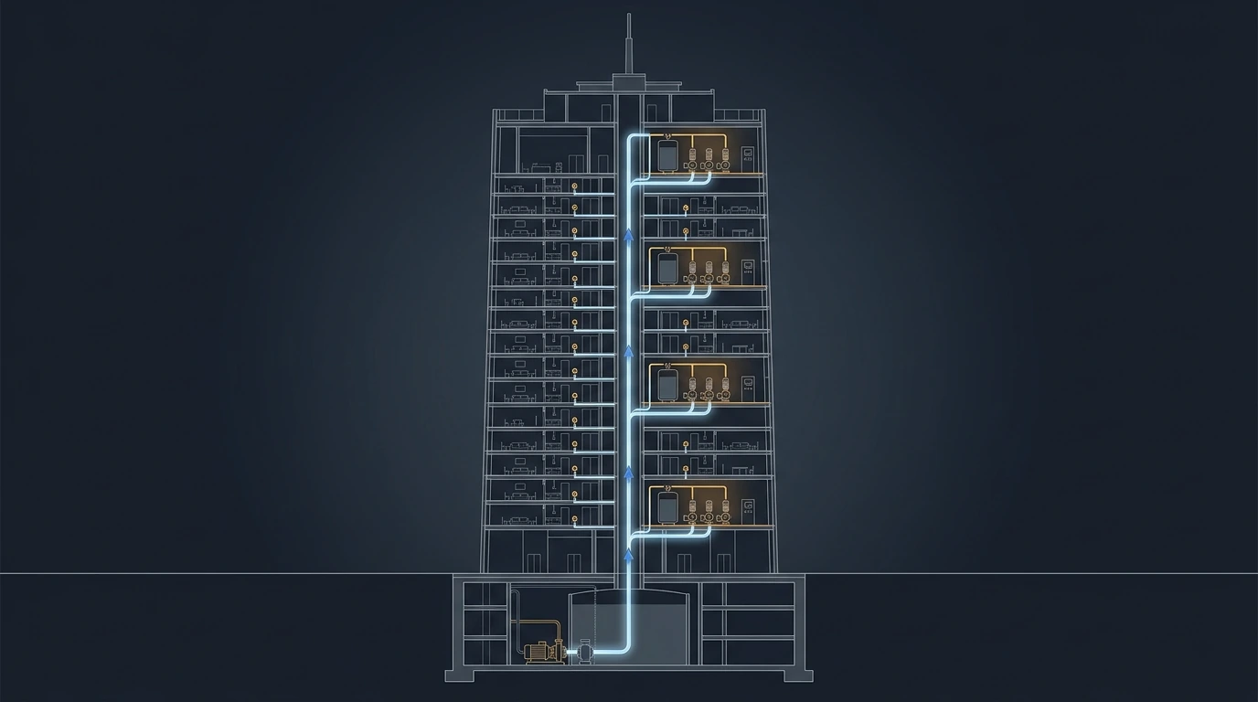
Fire water has to reach the top floor once, on the worst day of the building's life. Domestic water has to reach it every time somebody opens a tap, at a pressure that is neither a dribble nor a jet, for sixty years. That second requirement is far harder, and it is governed by a constraint fire systems never face: the acceptable pressure window at a tap is only about 3.5 bar wide, which is worth just 36 metres of building. A megatall tower is therefore not a four-zone problem like the standpipe — it is a seventeen-zone problem, unless you design your way out of it. On top of that sits a second, quieter error: almost every tall residential tower in the world is sized by a 1940 method that over-predicts peak demand by a factor of three.
1 · Why domestic water in a megatall is a different problem
- The pressure window is tiny. A tap needs roughly 1.0–1.5 bar flowing to work properly, and codes cap static pressure at a fixture at about 4.5–5.5 bar to prevent noise, splashing, seal wear and burst flexible connectors. That window is worth about 36 m of height — around ten storeys.
- Demand is probabilistic, not additive. Nobody flushes every toilet at once. The whole design rests on a statistical estimate of simultaneous use, and the traditional estimate is badly out of date for modern low-flow fittings.
- Water quality degrades with residence time. Large break tanks high in a tower can hold water for days. Chlorine decays, temperature drifts into the growth range, and a storage strategy sized purely for resilience becomes a public-health liability.
- Every fixture is a potential cross-connection. With hundreds of metres of head available, a backflow event does not trickle — it drives.
- The energy is real. Lifting water 600 m costs about 2.4 kWh/m³ at the pump shaft — roughly five times the specific energy of a typical municipal distribution system, for the last 600 m of a journey that may have started 400 km away.
The static-pressure physics is the same \(p=\rho g h\) that drives fire standpipe zoning; what changes is the ceiling. Fire equipment tolerates 12–24 bar. A shower mixer tolerates five.
2 · Estimating demand — and why Hunter over-sizes your tower
Roy Hunter's 1940 fixture-unit method is still the default in most codes. It models each fixture as an on/off process, assigns weighted water supply fixture units (WSFU), and reads a design flow off an empirical curve[1][2]. It was a brilliant piece of work — calibrated against the fixtures of 1940, which used a 20-litre flush, an unrestricted 15 L/min tap and no aerators at all.
Modern fittings use a 4.5-litre dual flush, 6 L/min aerated taps and 9 L/min showers. The fixtures changed by a factor of three; the curve did not. The modern replacement — the basis of the IAPMO Water Demand Calculator and of EN 806 / DIN 1988-300 style methods — treats simultaneous use as a binomial process[3]:
with \(n\) fixtures, \(p\) the probability any one is in use at the peak minute, \(q_f\) the flow of one fixture and \(z\) the confidence multiplier (1.96 for the 97.5th percentile). The first term is the average demand; the second is the statistical peak above it. Note what happens as \(n\) grows: the mean scales with \(n\) but the peak term only with \(\sqrt{n}\), so the bigger the tower, the smoother the demand — the exact opposite of what a per-fixture allowance implies.
3 · Interactive: Hunter vs the probabilistic method
Set the size of the tower and the fixture assumptions. The red curve is the classic Hunter fixture-unit estimate; the blue curve is the binomial estimate for the same building. The gap between them is pipe, pump and plant you may be buying for nothing.
A 250-unit tower comes out at 17.2 L/s on Hunter and 5.2 L/s on the binomial method — a factor of 3.3. That propagates into roughly double the riser diameter, a pump set three times too large running permanently at the wrong end of its curve, and a storage volume that turns over so slowly the water goes stale. Note also the shape: the two curves diverge as the building grows, because Hunter never learned that large populations average out. Codes still mandate Hunter in many jurisdictions — so calculate both, size the pipe to the code, and size the pumps and storage to reality, with the calculation on record.
4 · Pressure zoning — the 36-metre problem
Zoning domestic water is arithmetic. If the highest fixture in a zone needs \(p_{min}\) and the lowest may not exceed \(p_{max}\), then the tallest possible zone is:
With a 1.5 bar minimum and a 5.0 bar maximum that is 35.7 m — about ten storeys. A 600 m tower would need seventeen pressure zones, each with its own tank or pump set. Nobody builds that. The way out is to separate the two constraints:
- Let the riser carry high pressure, and break it at the floor. Run the riser at its pipe rating (PN16 with a 1.5 bar top residual → 148 m of column) and fit a floor or apartment pressure-reducing valve on each branch. The riser zone is now set by pipe class, not by tap comfort: five zones instead of seventeen. The PRVs become the most safety-critical, most numerous, least-maintained components in the building — which is the trade you are making.
- Use PRV cascades within a zone. Intermediate PRVs every few floors on the riser, each dropping the pressure back into the window, with the branch pressure checked at the top and bottom fixture of every PRV group.
- Exploit gravity down-feed. Feeding down from a high tank gives the top floors of the zone the low pressure they need naturally, with the highest pressures at the bottom of the down-feed where PRVs are easiest to group.
5 · Interactive: the pressure window and how many zones it costs
Set the acceptable fixture pressure window and the riser pipe class. The chart shows the pressure profile up the tower for two strategies: zoning purely on tap comfort, and zoning the riser on pipe class with floor PRVs doing the fine control. The shaded band is the acceptable fixture window.
The default case is stark: a 3.5 bar comfort window is worth 36 m, so a 600 m tower needs 17 tank-and-pump zones if the riser itself must stay inside the window. Zone the riser on PN16 instead and it falls to 5 — but you have now committed to roughly seventeen PRV groups per riser, one for every comfort-window's worth of height, every one of which must be scheduled, set, tested and maintained. Widen the window by a single bar and you save two or three zones; that is why the choice of tapware, and its permitted maximum pressure, is a decision the mechanical engineer should be making early rather than inheriting late.
6 · Supply architectures
- Gravity down-feed from high-level tanks. Transfer pumps lift water to tanks at the top of each zone or at the roof; the zones are fed downward by gravity through PRVs. Reliable — it keeps working through a pump or power failure, and the tank rides out demand peaks so the pumps see a smooth duty. The cost is structural (tanks high in a tower are heavy), spatial, and energetic, because every litre is lifted to the top whether it is used on floor 10 or floor 100.
- Zone-boosted (direct) pumping. A pump set per zone draws from a lower break tank and boosts only that zone. No high-level storage, much less structural load, and each litre is lifted only as far as it actually goes — roughly half the energy of a roof-tank scheme. In exchange the system depends entirely on pumps and power, so redundancy and standby generation become part of the water strategy.
- Cascade / series transfer. Ground tank → mid-level tank → upper tank, each stage lifting one zone height, exactly as in the fire system. Keeps every pump and pipe inside its pressure class and gives each stage a guaranteed suction source. Note carefully: cascading saves pressure class, not energy — the water still ends up at the same height, so the ρgh is unchanged.
- Hydropneumatic / variable-speed boosters. Multi-pump variable-speed sets on a small pressure vessel, holding a set-point. Compact and responsive; the vessel exists to stop the pumps hunting on tiny demands, not to store water.
7 · Interactive: the energy cost of height
Pumping water up a tower is one of the few building loads that is pure physics — you cannot design it away, only avoid wasting it. This compares lifting every litre to a roof tank against boosting each litre only to its own zone.
At 600 m the roof-tank scheme costs about 2.45 kWh/m³ and the zone-boosted scheme about 1.28 — roughly half, because demand is spread up the tower and the average litre only travels half way. For a 150 m³/day tower that is around 64 MWh a year. It is not a reason to abandon gravity feed, whose reliability and peak-smoothing are worth a great deal; it is a reason to stop lifting everything to the roof by default, and to consider a hybrid — gravity for the upper zones and direct boosting for the lower ones, which is what most well-engineered megatall towers actually do.
8 · Storage, turnover and water quality
Storage in a tall building is sized by three competing requirements, and the third is usually forgotten:
- Resilience — hours of supply if the town main fails. Drives volume up.
- Peak smoothing and pump duty — enough buffer that the transfer pumps run steadily rather than chasing demand. Drives volume up.
- Turnover and water quality — drives volume down. Chlorine residual decays exponentially; at typical temperatures a residual is largely gone within 2–3 days. Storage sized for a generous four-day outage is storage that delivers biologically active water on a normal Tuesday.
Design for a turnover of roughly one day across the whole storage chain, and get resilience from redundancy and multiple incoming connections rather than from volume. Compartment every tank into at least two cells so one can be cleaned without shutting the tower down, arrange inlets and outlets diagonally opposite so the tank actually flushes instead of short-circuiting, and never let a tank become a plug-flow dead volume with the inlet next to the outlet. Where residence time cannot be avoided, re-chlorinate or fit UV at the tank outlet and monitor the residual continuously.
9 · Backflow, cross-connection and material selection
- Protect by hazard category, at every zone boundary. An air gap (AA/AB) at the break tank is the only absolute protection and should be the primary barrier at the building inlet. Below that, RPZ valves for high-hazard connections — cooling towers, irrigation with fertiliser injection, water features, chemical dosing — and double check valves for lower-hazard ones. In a tower the risk is amplified: a burst on a low floor can pull a substantial vacuum on the riser above it.
- Fit vacuum breakers at the top of every riser. When a riser drains, it will try to siphon; without a vacuum breaker it pulls back through fixtures.
- Choose pipe for the pressure class and the water. Copper, stainless and PPR/PEX all behave differently at 16 bar and at 60 °C. Watch velocity limits for erosion-corrosion in copper (keep below ~1.5 m/s on hot recirculation), and check that plastic system pressure ratings are stated at the operating temperature, not at 20 °C — the de-rating is severe.
- Separate the fire and domestic storage, or prove the turnover. Shared tanks look efficient and create a large stagnant fire reserve inside the potable system.
10 · Transients in tall risers
A 600 m riser full of water is a substantial mass, and domestic systems are full of fast-closing devices — solenoid valves, ceramic-disc taps, washing machines. The Joukowsky pressure rise for an instantaneous stop is \( \Delta p = \rho a \Delta v\); with a wave speed of about 1,200 m/s in steel, a 1 m/s velocity change gives roughly 12 bar on top of whatever static pressure is already there. On a low floor of a tall zone that is enough to exceed the pipe rating[6]. Provide arrestors at fast-acting fixtures and at the ends of long branches, slow the closure of solenoid and motorised valves, and check the pump check-valve arrangement on trip. The full treatment of the physics is in valve closure and water hammer.
11 · Installation & execution tricks
- Schedule every PRV with two numbers — set-point at design flow and expected static at the lowest fixture — and commission against both. Record the as-set values; the single most useful document for the facilities team over the building's life.
- Fit isolation and a strainer upstream of every PRV, with a test point either side. A PRV you cannot isolate is a PRV nobody will ever service.
- Support the riser for weight and movement. A full DN150 riser is roughly 40 kg per metre with its water; over 150 m of zone that is six tonnes hanging on the shaft steel. Add thermal and structural movement and the anchor and guide design becomes a structural submission, not a bracket schedule.
- Chlorinate and flush systematically, bottom-up, and sample per zone. Partial disinfection of a zoned system is the classic reason a tower fails its microbiological clearance twice.
- Pressure-test by zone, at zone rating — testing the whole riser at the highest zone's pressure is how PN10 branch work gets destroyed before handover.
- Meter every zone. Zone-level metering is what turns an unexplained consumption rise into a located leak, and it costs almost nothing at construction. The rationale is the same as in non-revenue water: you cannot manage losses you cannot see.
- Prove the transfer control logic on site — level switches, pump duty rotation, low-level cut-out, and the alarm on tank overflow. Overflowing a tank on level 90 is an expensive way to discover a float switch was wired inverted.
12 · The design & installation checklist
- Calculate demand twice — code method for compliance, probabilistic method for reality; size pumps and storage on the second.
- Fix the pressure window early — agree the tapware maximum with the architect; it decides the zoning.
- Zone the riser on pipe class and control at the floor, unless the tower is short enough to zone on comfort alone.
- Check both ends of every PRV group — highest fixture flowing, lowest fixture static.
- Choose the architecture on energy and reliability together — hybrid gravity/boosted is usually the honest answer.
- Size storage for one-day turnover, get resilience from redundancy, compartment every tank.
- Protect against backflow by hazard at every boundary, with air gaps at the inlet and vacuum breakers at riser tops.
- Assess transients — arrestors, slow closure, and a check on the pump trip case.
- Commission on paper first — PRV schedules, zone test pressures, disinfection plan and zone metering, all issued before anyone opens a valve.
References & standards
- Hunter, R.B. Methods of Estimating Loads in Plumbing Systems, National Bureau of Standards Report BMS65 (1940) — the origin of the fixture-unit method.
- Uniform Plumbing Code (UPC) / International Plumbing Code (IPC) — fixture-unit schedules, maximum and minimum fixture pressures, PRV requirements; and the Saudi Building Code SBC 701 plumbing provisions.
- IAPMO Water Demand Calculator and its supporting research (Buchberger et al.) — probabilistic peak demand for modern low-flow fixtures; and DIN 1988-300 / EN 806-3 sizing methods.
- CIBSE Guide G — Public Health and Plumbing Engineering; and the Institute of Plumbing Plumbing Engineering Services Design Guide.
- ASHRAE Design Guide for Tall, Supertall, and Megatall Building Systems, 2nd ed. — vertical zoning of domestic water, storage location and transfer strategies.
- ASHRAE Handbook — HVAC Applications, Service Water Heating and Water Distribution chapters; and AWWA M14 Backflow Prevention and Cross-Connection Control.
- BS 8558 / BS EN 806 — design, installation, testing and maintenance of services supplying water for domestic use, including disinfection.
- WHO Water Safety in Buildings — storage turnover, residual management and microbiological risk in building water systems.