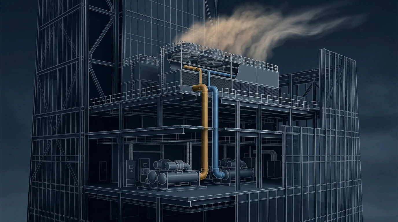
There is one line in a tall-building chilled-water schematic that behaves completely differently from all the others, and it catches out engineers who have spent their careers on closed systems. The condenser water circuit is open — it ends in a cooling tower basin that is exposed to atmosphere — so the return column does not push back. The pump lifts the full height, every second, forever. Put the chillers in the basement and the towers on the roof of a 300 m tower and you have just specified 817 kW of condenser pumping to move heat you could have moved for a tenth of that. This single distinction, more than any efficiency curve, is what dictates where heat rejection plant goes in a tall building — and in the Gulf it competes with a second constraint that is becoming the harder one: the towers will drink about 2,400 m³ of water a day.
1 · The open circuit: what cancels and what does not
In a closed chilled-water loop the water that goes up comes back down and the static head cancels, which is why a 600 m tower needs only tens of metres of pump head — the argument set out in chilled-water pumps. The condenser circuit is the one loop in the building with an open surface in it, and the near-universal assumption is that this breaks the cancellation. It does not — provided the return leg runs full and sealed back to the pump suction:
The break in the circuit sits at the top, where the water is at atmospheric pressure anyway. The rising column still has a falling column behind it, so the pump's differential head is friction, nozzle pressure and the short lift from the basin water level to the distribution header — not the height of the building. This is standard tower-pump sizing [1][2], and it is worth stating plainly because the opposite is asserted constantly.
What does not cancel is pressure. Static head that is recovered energetically is still present mechanically. Every metre between the plant and the tower basin puts 0.0981 bar on the condenser barrels, pumps, valves, strainers and gaskets at the bottom of the riser. At 150 m that is 14.7 bar — already past a standard 150 psi waterbox. At 600 m it is 59 bar, past anything in a catalogue.
And the cancellation is conditional, which is where the real risk lives. It is lost — completely — if:
- the return discharges into an open sump or break tank at plant level, which some designs do deliberately to escape the pressure class problem. The pump then really does lift the full height, permanently.
- the return riser runs part-full — undersized, badly vented, or air-bound — so only part of the column is working for you.
- Start-up. With an empty riser the pump must fill it against the full lift, running far out on its curve at a flow and NPSH it was never selected for. Size the motor and the check valve arrangement for that case, not just the running case.
- Shutdown drain-down. The riser empties back into the basin. The basin, or a dedicated drain-down tank, has to hold it — otherwise the tower overflows on every stop and the sump runs dry on every start.
Those four bullets, not the ρgh, are what drive the architecture:
- Chillers go near their towers — on a high mechanical floor immediately below a tower deck, or paired at intermediate levels. The reason is pressure class and drain-down volume, not pump power.
- Or the circuit gets closed. A plate heat exchanger between an open tower circuit and a closed building circuit converts the problem back into a closed one — at the cost of an approach, exactly the trade described for chilled water zoning.
- Or the towers come down. Podium-level or basement-intake towers with the chillers alongside, accepting the architectural and acoustic consequences.
- Closed-circuit (fluid) coolers avoid the open basin entirely, at a penalty in approach and footprint.
2 · Interactive: what the open circuit really costs
Set how far the tower basin sits above the condenser pumps. The blue line is the pump power when the return column is kept full and sealed — flat, because the static cancels. The red curve is the same duty once that column is broken. The dotted line, on the right axis, is the static pressure the plant sits at regardless of which case you are in.
Lift the basin 150 m above the pumps and the plant sits at 14.7 bar — past a standard 150 psi waterbox before anything else has happened — while the pump, if the return column is kept full and sealed, needs only 25 m of head and 63 kW. Break that column and the same duty costs 440 kW: a 377 kW continuous penalty, about 1,980 MWh a year, bought entirely with a hydraulic detail. So the open circuit's real cost is pressure class, and its real risk is whether the return leg stays full — at start-up, at part load, and after every trip. Closing the loop through a plate heat exchanger costs about 8 m of extra pumping (83 kW) and roughly 1 K of condenser approach, which is about 2.5 % on the chiller; what it buys is a building-side circuit that never sees the tower's static at all. That, not pump energy, is why the exchanger is usually the right answer above about 100 m.
3 · Approach, range and where the efficiency actually is
A cooling tower is defined by two temperature differences and one ambient condition[1][2]:
- Range — the temperature drop across the tower, equal to the rise across the condenser. Set by the flow rate for a given load: \( \text{range} = \dot{Q}/(\dot{m}c_p)\). Typically 5–6 K.
- Approach — how close the leaving water gets to the ambient wet-bulb temperature. This is the tower's real performance measure, typically 3–5 K. A closer approach means a physically larger tower, and the size grows steeply as the approach tightens; below about 2.5 K it becomes uneconomic.
- Wet bulb, not dry bulb. This is the number that matters, and it is where Gulf coastal sites are punished. Riyadh's summer design wet bulb is around 20 °C despite a 44 °C dry bulb; Jeddah's is around 29 °C. A tower in Jeddah delivering a 4 K approach produces 33 °C condenser water where the same tower in Riyadh produces 24 °C — and every one of those 9 K costs roughly 2.5 % of chiller power.
The design lever is that condenser water temperature and tower fan energy pull in opposite directions: a colder tower means a bigger, harder-working fan but a much more efficient chiller. The chiller is far larger than the fan, but fan power climbs steeply as the approach tightens, so the optimum is a real balance rather than a one-sided push — and its position is set by the fan-to-chiller power ratio, not by either machine alone. What is unambiguous is the operating case: a condenser-water reset that tracks the actual wet bulb is one of the highest-value control sequences in the plant, because for most of the year the wet bulb is far below design and the chiller will take every degree you give it.
4 · Interactive: approach, wet bulb & total plant power
Set the design wet bulb and the approach you are buying. The chart is total plant power — chiller plus tower fan — against approach, showing the optimum and how far it moves when the climate changes.
At a Jeddah wet bulb of 29 °C, a 4 K approach gives 33 °C condenser water and about 1,419 kW of combined plant power, with the optimum sitting at 4.9 K. The balance is genuine rather than one-sided: the chiller is fourteen times the size of the fan, but the fan power rises steeply as the approach tightens, so the two meet near 5 K. What moves the answer is the ratio — halve the fan power and the optimum falls to 3.8 K; double it and it climbs to 6.4 K. Drop the wet bulb to Riyadh's 20 °C and the whole curve falls by roughly a fifth for the same building: the same tower and the same chiller are a fundamentally different plant on the coast than they are inland. Design the tower for the site's wet bulb, not for a regional average, and reset the condenser set-point against measured wet bulb in operation.
5 · Water — the constraint that is overtaking energy
A cooling tower rejects heat mainly by evaporating water, and that water is consumed. The arithmetic is simple and the totals are startling[3]:
where \(E\) is evaporation, \(B\) blowdown and \(M\) makeup, and cycles of concentration (CoC) is how many times the dissolved solids are allowed to concentrate before water is dumped. A 50 MW tower evaporates 75 m³/h no matter what you do — that is physics — but the blowdown is entirely a water-treatment decision: at two cycles it is another 75 m³/h, at six cycles just 15. Raising the cycles from 2 to 6 saves 1,440 m³ a day on a single plant, which in a water-scarce region is a far more valuable saving than most energy measures.
A 50 MW plant at four cycles consumes 100 m³/h — 2,400 m³ a day, comparable to the domestic demand of several thousand people. Push the cycles from 2 to 6 and the makeup falls from 150 to 90 m³/h with no change to the towers at all, purely through a better treatment programme and tighter conductivity control. In the Gulf this is where the real design conversation is heading: side-stream filtration, higher cycles, treated sewage effluent or condensate as makeup, and in some projects the decision to accept air-cooled chillers and their energy penalty rather than consume the water at all.
6 · Placement, wind and plume
- Give the tower its air. Towers are volumetric air machines; they need unobstructed intake on all sides and a clear discharge path. Recirculation — hot moist discharge re-entering the intake — raises the effective wet bulb and silently destroys performance. Check separation from parapets, screens and adjacent towers, and treat architectural screening as an aerodynamic element requiring free area, not as cladding.
- Wind at height changes the answer. A tower deck 300 m up sits in the wind field described in outdoor air and ventilation. Cross-wind can strip the discharge plume down the leeward face, drive drift onto the façade and into intakes, and unbalance cells within a bank.
- Drift and plume are contamination and nuisance risks. Specify high-efficiency drift eliminators (0.001 % or better), check the plume against fresh-air intakes, helipads and openable windows, and consider plume-abated towers where visible plume is an issue.
- Structure and access. A tower bank full of water is a heavy, dynamic, vibrating load on the highest part of the building. Coordinate the wet operating weight and the seismic and wind case with the structural engineer early, and design a maintenance route for fill replacement and motor changes at that level.
- Freeze and shutdown. Even in the Gulf, basin heaters and a proper drain-down strategy matter for winter partial load; more importantly, plan the isolation and drain sequence for a cell taken out of service without shutting the plant.
7 · Water treatment and Legionella
A cooling tower is a warm, aerated, nutrient-rich aerosol generator located near fresh-air intakes and public space. Control is a designed system, not a maintenance activity[4]:
- Design out stagnation. No dead legs, no idle standby cells left wet and unturned, and a basin arrangement that actually turns over. Rotate standby cells automatically.
- Automate the treatment. Conductivity-controlled blowdown, proportional biocide dosing with two alternating biocides, corrosion and scale inhibitor, all monitored and trended rather than dosed on a visit schedule.
- Side-stream filtration to remove the solids that both foul the fill and shelter organisms from biocide.
- Sample and record. Routine dip-slides and Legionella sampling with the results trended, and a written water safety plan naming the responsible person.
- Design for cleaning. Basins that can be drained, accessed and physically cleaned, with removable fill packs — this is the item most often designed out for space and most often needed.
8 · Installation & execution tricks
- Set the basin level and the pump suction together. Condenser pumps need positive suction and adequate submergence; check the NPSH available at the highest basin level and, critically, at the lowest operating level during a rapid load change.
- Equalise multi-cell basins properly. Under-sized equalisation lines are the classic cause of one cell overflowing while another starves and draws air.
- Provide a proper flooded start and a drain-back volume. When the pumps stop, the water in the risers comes back; the basin must accept it without overflowing. Size the freeboard for the full drain-back, not for the static level.
- Fit isolation, strainers and test points on every cell, and a permanent flow meter on the condenser circuit — condenser flow is the most commonly wrong and least measured number in a chiller plant.
- Clean and passivate before handover. New galvanised towers need a controlled passivation period at moderate pH; skip it and white rust starts in the first month.
- Do not commission on a mild day and call it done. Tower capacity is only meaningful at the design wet bulb; where that cannot be achieved, test at the achievable wet bulb and correct to design using the manufacturer's performance curves, and record both.
- Protect the fill during construction. Construction debris and site water in a new tower ruins the fill and seeds the system biologically before it is ever handed over.
9 · The design & installation checklist
- Prove the return column — full, sealed and vented correctly, so the static actually cancels; then check the start-up and drain-down cases separately, because that is where it does not.
- Size the condenser side on pressure class — locate chillers near their towers or close the loop with a plate heat exchanger, and never let a waterbox inherit hundreds of metres of static by default.
- Design on the site wet bulb, and check what the approach is really worth against chiller power.
- Optimise approach on total plant power, not on tower first cost — the answer is colder than it looks.
- Specify condenser-water reset against measured wet bulb, with the chiller's minimum entering temperature respected.
- Compute the water balance and design the treatment for high cycles; evaluate alternative makeup sources.
- Give the towers air — free intake, clear discharge, screening treated aerodynamically, recirculation checked.
- Check plume and drift against every intake, opening and helipad.
- Design the Legionella control system, not just the dosing contract.
- Coordinate the wet weight and dynamics with the structural engineer, and design the maintenance route.
- Commission with correction to design wet bulb, and passivate before handover.
References & standards
- ASHRAE Handbook — HVAC Systems and Equipment, Cooling Towers chapter — range, approach, wet-bulb performance and tower types.
- Cooling Technology Institute (CTI) ATC-105 Acceptance Test Code for Water Cooling Towers and CTI certification standards — performance testing and correction to design conditions.
- ASHRAE Handbook — HVAC Applications, Water Treatment chapter — cycles of concentration, blowdown, scale and corrosion control, side-stream filtration.
- ASHRAE Standard 188 Legionellosis: Risk Management for Building Water Systems and ASHRAE Guideline 12; HSE ACOP L8 and HSG274 Part 1 for evaporative cooling systems.
- ANSI/ASHRAE/IES Standard 90.1 — condenser water reset, tower fan control and minimum equipment efficiency.
- ASHRAE Design Guide for Tall, Supertall, and Megatall Building Systems, 2nd ed. — heat rejection plant location and condenser water strategy in tall buildings.
- ASHRAE Handbook — Fundamentals, Climatic Design Information — design wet-bulb data by location.
- Saudi Building Code SBC 501 and Saudi water regulations on cooling tower makeup, alternative water sources and discharge.