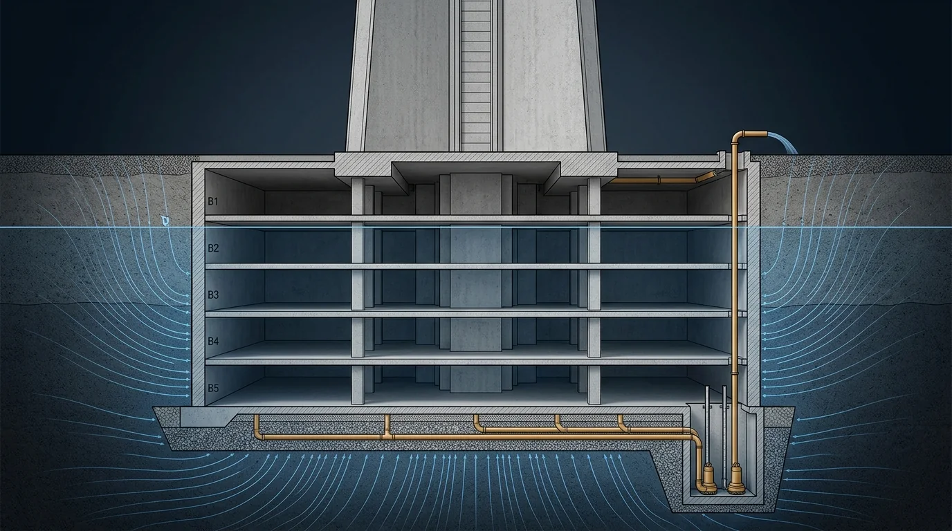
Every megatall tower sits on a deep basement, and every deep basement sits below the water table. That creates two problems that behave nothing like each other. One is flow: how much water arrives, which depends almost entirely on the ground and barely at all on the building — the same 20 m excavation takes 3 L/s in silt (k = 10⁻⁶ m/s) and 326 L/s in clean sand (k = 10⁻³ m/s), a factor of a hundred set by a soil parameter the MEP engineer does not control. The other is pressure: a water table 30 m above the slab pushes up at 294 kPa — thirty tonnes on every square metre — and that is a structural decision the drainage design must be coordinated with, not a pumping problem at all.
1 · Two strategies, decided by somebody else
Before any pump is sized, the project has chosen one of two fundamentally different approaches, usually on structural and geotechnical advice:
- Tanked (fully waterproofed). The basement is a sealed box designed to resist the full hydrostatic uplift and lateral pressure. No permanent dewatering. The structure carries everything, the waterproofing must be perfect for the life of the building, and the MEP scope reduces to handling leakage, groundwater ingress at joints and the internal drainage.
- Drained (under-slab drainage with permanent pumping). A drainage layer beneath the slab relieves the pressure, and pumps run forever to keep the water down. Structural cost falls sharply; in exchange the building acquires a permanent, safety-critical pumping system that must never fail, with all the redundancy, power and maintenance obligations that implies.
The choice is a whole-life trade between concrete and pumps, and the MEP engineer's job is to make the second half of that trade honest — because the pumping obligation is routinely under-stated at the point the decision is made. A drained basement means N+1 pumps on essential power, alarmed, tested, and maintained for sixty years, plus the energy, plus the consequence of a failure that floods the plant rooms containing the building's entire mechanical and electrical infrastructure.
2 · Interactive: how much water actually arrives
Steady seepage into an excavation is governed by Darcy's law. Using the classical unconfined-flow approximation with Sichardt's radius of influence:
with \(k\) the permeability (m/s), \(H\) the drawdown, \(r\) the equivalent excavation radius and \(R\) the radius of influence. Note where the sensitivity lies: \(Q\) is linear in \(k\), and \(k\) ranges over six orders of magnitude between clay and gravel.
The chart is a warning as much as a calculator. A 20 m drawdown over a 40 m radius takes about 3 L/s in silt (k = 10⁻⁶ m/s) and 326 L/s in clean sand (k = 10⁻³ m/s) — the same building, the same excavation, a hundredfold difference driven by a parameter that is measured, not designed. Two consequences: never size a permanent dewatering system from a soil description, only from a pumping test; and note the radius of influence, which at high permeability reaches kilometres — permanent dewatering in a permeable aquifer draws down neighbouring ground, and settlement of adjacent structures is a real and litigated risk that belongs in the design discussion.
3 · Interactive: uplift, and why the drainage layer exists
Twenty metres of water above the slab is 196 kPa. Against a 2 m raft and 60 kPa of load above, the net uplift is 88 kPa — which over a 1,000 m² footprint is 9,000 tonnes trying to lift the building. That is resisted by thickening the raft, by tension piles or anchors, or by removing the pressure altogether with an under-slab drainage layer. Drag the relief slider and watch the net uplift fall to nothing: that is exactly what a drained basement buys, and exactly why its pumps are structural elements in everything but name. A drained basement whose pumps fail does not merely flood — it can float.
4 · Interactive: sump sizing and the energy of depth
Sump design is the same cycle-time problem as any wet well: too small and the pumps short-cycle and burn out, too large and the water stagnates. The classic result is that the active volume needed is greatest when the inflow is half the pump capacity.
A 40 L/s duty pump at ten starts an hour needs 3.6 m³ of active volume — and lifting from 25 m costs 0.168 kWh/m³, which running at half duty all year is about 106 MWh. Two design points follow. Raise the permitted starts and the sump shrinks, but check it against the motor rather than assuming; and note that the specific energy is modest per cubic metre but the volumes in a permeable site are enormous — at 326 L/s the same 25 m lift is a continuous 197 kW load, which belongs in the building's energy model and its essential-power sizing, not in a footnote.
5 · The rest of the basement drainage
Groundwater is only one of the inflows a deep basement has to handle, and the others arrive suddenly:
- Ramp and vehicle entrance water. The single largest transient inflow. Size the ramp channel and its sump for the design storm falling on the whole ramp catchment plus the wash-off from vehicles, and provide a physical high point at the top of the ramp so a surcharged street cannot run in.
- Sprinkler and firefighting water. A design discharge in a basement produces a very large flow with nowhere to go. Codes and insurers increasingly require the drainage to handle a defined firefighting flow for a defined duration — check the number and design for it, because it usually exceeds every other case.
- Plant room leakage and washdown. Bunded, drained plant rooms with alarmed gullies, discharging to a sump that is not the groundwater sump.
- Separate the streams. Groundwater is clean and can often be discharged directly or reused; car park and ramp water carries oil and silt and needs interception; foul drainage must be separately pumped and must never be able to back up into either. Three systems, three sumps, no cross-connections.
- Oil interception and silt traps on the car park system, sized and — critically — accessible for the regular emptying they need.
- Backflow protection on every discharge. A public sewer that surcharges in a storm will drive water down into the lowest point of the building, which is where all the plant is. Non-return devices, anti-flood valves and a discharge point above the surcharge level where possible.
6 · Groundwater as a resource
In a water-scarce region, pumping thousands of cubic metres a day of clean groundwater to waste is difficult to defend. Depending on quality and local regulation it can serve cooling tower makeup — where a 50 MW plant drinks 2,400 m³ a day — or irrigation, water features or toilet flushing through a treatment train. Three cautions: test the quality properly (deep groundwater is often saline or high in sulphates and can be aggressive to both plant and concrete); confirm abstraction and discharge consents, which in many jurisdictions are the binding constraint rather than the engineering; and design the reuse so the dewatering function is never compromised by a fault in the reuse system — the pumps must always be able to discharge to waste.
7 · Installation & execution tricks
- Insist on a pumping test, not a borehole description. Permeability inferred from soil classification can be an order of magnitude out, and the system is linear in it.
- Design the transition from temporary to permanent dewatering as a deliberate operation. Construction dewatering runs for years; the permanent system takes over at a moment when the basement is full of finished plant, and that handover is a high-risk event that needs a method statement.
- Make the sumps maintainable. Guide rails and lifting chains on submersible pumps so a pump can be withdrawn without entry, a permanent lifting point above each, and access covers sized for the pump — not for the man.
- Treat sumps as confined spaces in the design: ventilation, gas monitoring where foul is involved, and a maintenance procedure that does not require entry for routine work.
- Alarm at three levels — high, high-high and pump-fail — to a permanently manned location, and prove the alarm path at commissioning rather than the alarm contact.
- Rotate duty automatically and log run hours per pump; a standby that has sat idle for two years is not a standby.
- Protect the plant rooms. Raise plinths for electrical and control equipment in the lowest basement, provide a bunded threshold at plant room doors, and locate transformers and switchgear above the credible flood level where the layout allows it.
- Record the as-built drainage layer. Under-slab drainage cannot be inspected; its layout, outlets and rodding points must be documented at construction or they are lost forever.
8 · The design & installation checklist
- Establish tanked or drained early, and make the whole-life pumping obligation explicit in that decision.
- Size from a pumping test, with a design factor for heterogeneity.
- Check the radius of influence and the settlement risk to neighbours.
- Coordinate uplift with the structural engineer and confirm what the drainage layer is assumed to relieve.
- Design the pumps as safety-critical — duty/standby/standby, essential power, tested changeover, automatic rotation, three-level alarms.
- Separate groundwater, car park and foul into three systems with no cross-connection.
- Design for the firefighting discharge case, which often governs.
- Protect against sewer surcharge on every discharge.
- Evaluate groundwater reuse, subject to quality and consents, without compromising the dewatering duty.
- Plan the temporary-to-permanent handover and protect the plant rooms with plinths and thresholds.
References & standards
- CIRIA C750 Groundwater control: design and practice — dewatering design, permeability, radius of influence and settlement effects.
- CIRIA C515 / C760 and BS 8102 Code of practice for protection of below ground structures against water from the ground — tanked, drained and integral protection, and grades of waterproofing.
- Powers, J.P. et al. Construction Dewatering and Groundwater Control — theory and practice of seepage estimation and system design.
- ASHRAE Handbook — HVAC Applications and CIBSE Guide G — basement drainage, sump design and pumped drainage systems.
- BS EN 12056-4 and BS EN 752 — wastewater lifting plants and drain and sewer systems outside buildings, including surcharge protection.
- NFPA 13 / NFPA 20 and insurer guidance (FM Global) — drainage provision for sprinkler and firefighting discharge in basements.
- Hydraulic Institute ANSI/HI 9.8 Rotodynamic Pumps for Pump Intake Design — sump geometry, submergence and approach conditions; see also wet well vortex design.
- Saudi Building Code SBC 701 and local abstraction and discharge regulations governing groundwater reuse.