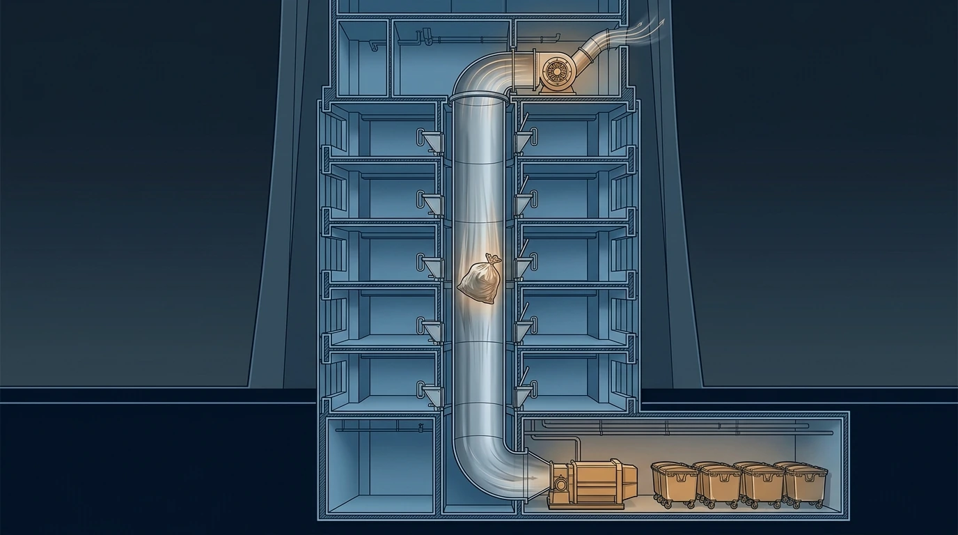
A refuse chute is the only system in a tall building deliberately designed to drop objects hundreds of metres in free fall. A five-kilogram bag reaches terminal velocity of about 28.6 m/s — 103 km/h — and it gets to 87 % of that within the first sixty metres, so a 600 m chute and a 60 m chute deliver almost identical impact: roughly 2,000 joules, arriving repeatedly, at the bottom of a shaft that runs the full height of the building. That shaft is simultaneously a fire path, an odour path and — because it is warm, vertical and hundreds of metres tall — a chimney developing 200 Pa of its own stack pressure. It is also, invariably, the last riser to be coordinated.
1 · Four problems in one shaft
- Impact. The energy arriving at the base is set by terminal velocity, not by building height, and it must be absorbed by something designed for it rather than by the floor slab.
- Fire. A vertical shaft full of combustible material connecting every floor is exactly the vertical fire spread compartmentation exists to prevent, and every hopper door is a penetration of a fire-rated enclosure.
- Odour and hygiene. The chute's own stack effect drives air — and everything in it — upward, out through hopper doors on the upper floors. This is the same physics as stack effect and it is solved the same way: by controlling the pressure regime, not by sealing harder.
- Noise. A bag at 100 km/h in a steel tube adjacent to bedrooms is a serious acoustic problem, and it arrives at night.
2 · Interactive: how fast, and how hard
A falling bag accelerates until drag balances weight. Integrating the equation of motion gives the velocity after a drop \(h\):
The curve flattens fast: a bag reaches 90 % of terminal velocity within about 70 metres, so everything above that height is hydraulically identical. A 600 m chute is not six times worse than a 100 m one — it is the same, which is genuinely good news and means the base detail is a standard problem rather than a megatall one. What it must handle is around 2,000 J per bag, repeatedly: that requires a designed speed-reduction or shock-absorbing base — a discharge chamber with a sacrificial impact plate, a compactor hopper designed for the energy, or an in-chute retarding device — not a bin sitting on a slab. Note the mass slider: hotel and commercial waste at 10 kg per bag more than doubles the energy.
3 · Interactive: what arrives at the bottom, and where it goes
Two thousand people generate 3.6 tonnes and 30 m³ a day loose — a 60 m³ store for a two-day collection interval, which at 3 m clear is 20 m² of bin space alone, before circulation, before the compactor, before the recycling streams and before a vehicle can turn. Compaction is what makes this fit: at 4:1 the same store is 15 m³. But a compactor is a powered machine in a wet, corrosive room with its own noise, power, drainage, maintenance access and a bin-change operation that must not block the chute — and it needs a control interlock so the chute cannot discharge onto a machine mid-cycle or into a missing bin.
4 · The chute as a chimney
The chute is warm, vertical and connects every floor to a refuse room — the ideal conditions for the stack effect described elsewhere in this series. A 400 m chute only 15 K warmer than outside develops around 208 Pa, all of it pushing air, odour and airborne material up and out through the hopper doors of the upper floors. The controls are all pressure controls:
- Extract at the top, mechanically. A continuously running extract fan at the chute head holds the whole shaft at negative pressure relative to the lobbies, so air moves into the chute at every hopper rather than out of it. This is the primary control and everything else supports it.
- Make-up at the bottom. The extract needs a designed air path in at the refuse room, or the fan simply pulls harder on the hopper doors and the negative pressure collapses.
- Self-closing, gasketed hopper doors with an interlock so only one can be open at a time on a given riser — which also prevents a bag being dropped onto somebody loading below.
- Wash-down and drainage. Chutes need periodic cleaning; provide a wash-down head at the top, a drained base and a gully in the refuse room connected to the foul system with a trap that will not dry out.
- Do not rely on sealing alone. A 200 Pa driving pressure will find every gasket; the answer is to reverse the pressure, not to fight it.
5 · Fire strategy
- The shaft is a fire-rated enclosure for its full height, with the rating maintained at every hopper door and every penetration.
- Sprinkler protection inside the chute — typically at the top, at the discharge and at intervals — with the discharge draining safely rather than flooding the refuse room's electrical equipment.
- Hopper doors are fire doors. Self-closing, rated, and with a fusible or automatic closing arrangement at the discharge so a fire in the refuse room cannot propagate up the shaft.
- The refuse room is a high fire load in its own right: separately compartmented, sprinklered, with detection and with a ventilation strategy that does not feed a fire.
- Interlock the chute on alarm. A fire condition should close the discharge and lock the hopper doors — a chute left open during a fire is an open vertical path.
6 · Interactive: the noise problem
A bag impacting at 100 km/h in a steel tube radiates structure-borne noise into every wall the chute touches. Because the chute is usually in the core, those walls are usually apartment walls.
The model here is indicative rather than predictive — real impact noise needs measurement or a manufacturer's data — but the ranking is not in doubt, and it makes the design point: enclosure alone does not get there, and the structure-borne path through the chute's fixings is what actually reaches the bedroom. Resiliently mount the chute within its shaft, do not let it touch a party wall, and — most effectively of all — locate it away from bedrooms in the first place, which is a core-planning decision made long before anyone calculates a decibel. The same principle as in vibration and noise control: the flanking path beats the barrier.
7 · Recycling, and the multi-stream problem
A single chute delivers a single mixed stream, which is increasingly unacceptable and in many jurisdictions non-compliant. The options each carry a design consequence:
- Multiple chutes. Simplest and most reliable, and the most expensive in core area — two or three full-height rated shafts instead of one.
- A single chute with a diverter at the base, selected by the user at the hopper. Saves shaft space but introduces a mechanism at the bottom of a 300 m drop, and depends entirely on users selecting correctly.
- Chute for general waste plus room-level collection for recyclables. Pragmatic and common, but it moves the problem into the operations budget and requires storage on every floor or a portering regime.
- Vacuum waste collection. Pneumatic transport from chute bases to a central terminal, avoiding vehicle movements through the podium entirely. Genuinely elegant on a large mixed-use development, high capital cost, high energy, and it needs a level of maintenance capability that must be verified before it is specified.
Whichever is chosen, decide it at concept stage. Adding a second full-height rated shaft to a tower after the core is set is not a variation; it is a redesign.
8 · Installation & execution tricks
- Reserve the shaft and the refuse room at concept, including the vehicle access, turning and bin-presentation route, which is a traffic-engineering constraint as much as an MEP one.
- Specify a designed discharge arrangement — impact absorption, a bin that cannot be missing, and an interlock that stops discharge during a bin change.
- Run the extract fan continuously and prove the negative pressure at the top and bottom hopper at commissioning, not just the fan's flow rate.
- Detail the acoustic isolation of the chute from the shaft explicitly, and check on site that no fixing bridges it — this is the same grout-bridge failure as under an inertia base.
- Provide wash-down and drainage at the top and the base, with a trapped, primed gully.
- Commission the fire interlocks — hopper locking, discharge closure and sprinkler operation — as part of the integrated systems test, not as a separate contractor's demonstration.
- Write the cleaning and maintenance regime into the O&M with intervals, and design the access it needs — a chute that cannot be cleaned becomes the source of the odour complaint the extract system is blamed for.
9 · The design & installation checklist
- Decide the waste strategy at concept — number of streams, chute count, vacuum or conventional.
- Design the discharge for the impact energy, which is set by terminal velocity, not by height.
- Size the store on real generation rates and a realistic collection interval, with compaction if the room will not otherwise fit.
- Hold the chute at negative pressure with continuous top extract and a designed make-up path.
- Rate the shaft for its full height, with rated self-closing hopper doors and in-chute sprinklers.
- Interlock on fire alarm and prove it in the integrated test.
- Isolate the chute acoustically and keep it away from bedrooms.
- Provide wash-down, drainage and cleaning access.
- Coordinate the vehicle route and bin presentation with the traffic strategy.
References & standards
- BS 5906 — Waste management in buildings: Code of practice: chute design, storage sizing, generation rates and collection.
- NFPA 82 — Standard on Incinerators and Waste and Linen Handling Systems and Equipment: chute construction, fire rating, sprinkler protection and discharge arrangements.
- International Building Code and Saudi Building Code SBC 801 — rubbish and linen chute provisions, shaft enclosure and access room requirements.
- CIBSE Guide G — Public Health and Plumbing Engineering — refuse systems, chute ventilation and refuse room services.
- ASHRAE Handbook — HVAC Applications and CIBSE Guide B2 — extract ventilation and odour control for waste handling areas.
- BS 8233 and CIBSE Guide B4 — noise criteria and structure-borne transmission relevant to chute location and isolation.
- Manufacturer design guidance for refuse chutes, retarding devices, diverters and compactors, and for pneumatic (vacuum) waste collection systems.
- Local municipality waste regulations governing stream separation, storage and collection access.