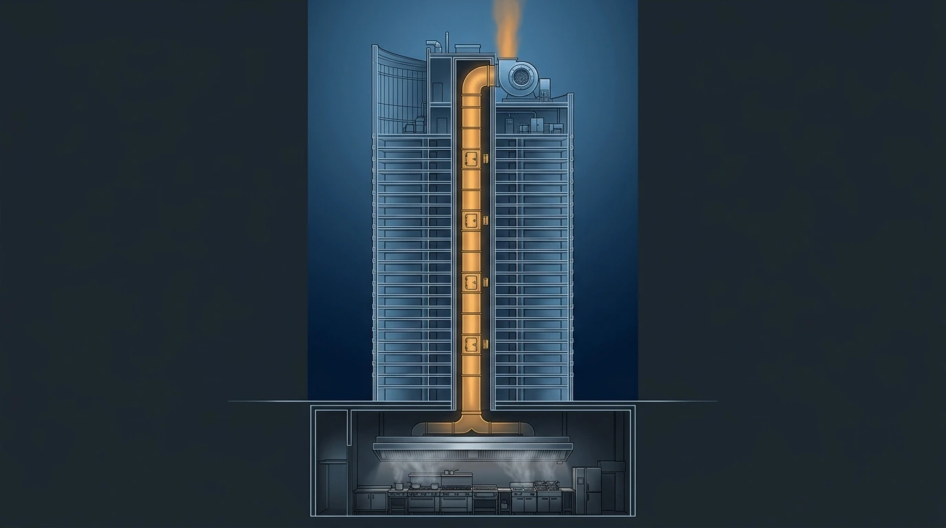
A mixed-use tower puts restaurants on the podium, a signature dining floor near the top, and staff kitchens somewhere in between — and every one of them needs a duct that runs, unbroken and uninterrupted, from the hood to the roof. That duct is lined with a combustible deposit, passes through occupied floors for hundreds of metres, and is one of the few elements in a tall building that is simultaneously a ventilation system, a fire hazard and a fire-rated compartment. It is also governed by a rule that no other duct in the building obeys: it has a minimum velocity, not just a maximum, and if the flow falls below it the grease stops travelling and starts accumulating.
1 · Why a grease riser is not a duct
- It carries fuel. Grease-laden vapour condenses on the duct wall. Over months it builds a layer that will sustain a fire the length of the riser, and a grease fire in a 300 m vertical duct is exactly the vertical fire spread a tall building is designed to prevent.
- It must be continuously welded and liquid-tight. No slip joints, no sealant-dependent seams, sloped back to the hood or to a drain point so condensate cannot pool in the run.
- It must be enclosed in a fire-rated shaft for its full height with a rated wrap or construction, and it cannot share that shaft with anything else.
- It has a minimum transport velocity. Codes require the air to move fast enough to keep droplets entrained — around 2.5 m/s absolute minimum, with 7.5–12.5 m/s the practical design range. This is the constraint that makes variable-flow kitchen ventilation difficult.
- It must be cleanable along its entire length. Access doors at every change of direction and at intervals up the riser — and in a tall building that means a cleaning route somebody has to physically reach, floor by floor, for the life of the building.
2 · Interactive: hood duty and riser size
Exhaust rate follows the hood type and the appliance duty beneath it; the duct then follows from the transport velocity you choose.
A heavy-duty 8 m canopy needs 4.8 m³/s, which at 10 m/s is a 782 mm round equivalent — and once wrapped, enclosed and given clearance it consumes about 1.2 m² of shaft for the full 200 m to the roof. Push the velocity up to save shaft area and the friction climbs with the square: the same riser at 14 m/s costs roughly twice the fan pressure. Two design consequences follow. First, the shaft must be reserved from concept, because it is unbroken and cannot be re-routed later. Second, group kitchens so they can share a riser only where a fire strategy permits it — every additional independent riser is another permanent hole through the core.
3 · Interactive: the turndown trap
Kitchen exhaust is the largest single air consumer in a restaurant and an obvious candidate for demand control — hoods sense cooking activity and modulate. But grease ducts have a floor below which they stop transporting, and a variable-flow system that ignores it is building a fuel load in a shaft.
Design at 10 m/s and you can turn down to 25 % before the velocity reaches the 2.5 m/s floor — and at 50 % flow the fan is already drawing only 12 % of its design power. That is the case for demand-controlled kitchen ventilation in one line: the savings are enormous and they are available well above the safety limit. The design move that unlocks it is to choose a higher design velocity deliberately, because the turndown range you get is the ratio between design and minimum velocity. Design at 7.5 m/s and you only reach 33 %; design at 12.5 m/s and you reach 20 %. Then set the control minimum in the BMS at the velocity limit, not at the fan's minimum speed, and alarm if it is ever violated.
4 · Interactive: make-up air and what a shortfall does
Every cubic metre extracted must be replaced. If the dedicated make-up air is short, the kitchen draws the difference from wherever it can — the restaurant, the lobby, the lift shaft — and a tall building has a very large reservoir to be pulled from.
Providing 85 % dedicated make-up leaves a 0.72 m³/s shortfall — deliberately, so the kitchen stays slightly negative and odours do not migrate into the restaurant. With a reasonable opening area that is only a few pascals, which is exactly right. Drop the make-up to 60 % and the kitchen goes strongly negative, doors become hard to open, the hoods lose capture because air is arriving sideways through the doorway rather than from the make-up plenum, and in a tall building the deficit is ultimately drawn down the lift shaft. Note the last readout: conditioning 4 m³/s of humid Gulf outdoor air is over 260 kW of cooling — which is why partially untempered or evaporatively cooled make-up air, delivered locally at the hood, is worth designing properly rather than dumping the whole load on the building's chilled water.
5 · Fire strategy for the riser
- The hood suppression system protects the hood and the first part of the duct, not the riser. Wet-chemical systems discharge at the plenum and the duct collar; the 200 m above them is protected by construction and by cleaning, not by suppression.
- The shaft rating is the primary protection. A continuously rated enclosure or an approved duct wrap for the full height, with the rating maintained at every penetration and every access door.
- The fan runs during a fire in most strategies, to keep the fire in the duct rather than let it spill into the hood — so the fan, its motor, its supports and its power supply must all survive the temperature. Check this explicitly; it is often assumed and rarely specified.
- Do not fit fire dampers in a grease duct. They collect grease, they fail, and they defeat the extract when it is most needed. Protection is by enclosure, not by damping.
- Discharge at the roof, away from intakes. High-velocity vertical discharge, well clear of any fresh-air intake, the helipad and any openable window — the dispersion check described in outdoor air and ventilation applies here more than anywhere.
- Grease removal at the hood is what protects everything downstream. High-efficiency baffle or cartridge filters, or a UV/ozone system where the riser is long and access is hard, reduce what reaches the duct in the first place. On a 200 m riser this is not a refinement — it is the main line of defence.
6 · Installation, cleaning & execution tricks
- Reserve the shaft at concept, and defend it. A grease riser cannot be re-routed, cannot share a shaft, and cannot be offset casually — every offset is a grease trap and an access door.
- Design the cleaning route before the duct. Access doors at every change of direction and at regular intervals up the riser, each one reachable from a floor or a platform. If the cleaning contractor cannot reach an access door, that section will never be cleaned and will eventually be the fire.
- Weld it continuously and test it. Liquid-tight, continuously welded external seams, light-tested or equivalent, with the test recorded per section as it is built — you cannot inspect it afterwards.
- Slope the duct and provide a drain point. Horizontal runs graded back to the hood or to an accessible residue trap, never to a low point buried in a ceiling.
- Insulate and clear the rating. Maintain the specified clearance to combustibles or the approved wrap system, and coordinate that clearance in the shaft before other trades fill it.
- Balance the hood at the hood. Capture and containment is proved by smoke test at the hood face with the make-up running, not by measuring the duct flow — a hood can be at design flow and still fail to capture if the make-up air is arriving from the wrong direction.
- Commission the demand control against velocity. Verify the minimum-flow setting corresponds to the code transport velocity, and prove the alarm.
- Hand over a cleaning schedule with frequencies by duty — heavy-duty solid-fuel or wok cooking needs far more frequent cleaning than a light-duty pastry kitchen, and the schedule should name intervals and access points.
7 · The design & installation checklist
- Reserve a dedicated, unbroken, fire-rated shaft per riser at concept stage.
- Size on hood duty, then choose the transport velocity deliberately to buy the turndown range you want.
- Set the demand-control minimum at the velocity limit, not at the fan minimum, and alarm it.
- Provide 80–90 % dedicated tempered make-up, delivered so it does not disturb capture.
- Check the kitchen’s pressure relationship to adjacent spaces and to the building.
- Maximise grease removal at the hood — the riser can only be protected by what never enters it.
- Rate the enclosure for the full height; no fire dampers in the duct.
- Confirm the fan survives fire conditions, with its power supply.
- Design and prove the cleaning access, and issue a duty-based cleaning schedule.
References & standards
- NFPA 96 — Standard for Ventilation Control and Fire Protection of Commercial Cooking Operations: duct construction, transport velocity, access, clearance and cleaning.
- ASHRAE Handbook — HVAC Applications, Kitchen Ventilation chapter — hood types, exhaust rates, capture and containment, make-up air strategies.
- ASHRAE Standard 154 — Ventilation for Commercial Cooking Operations; and ASTM F1704 for hood capture and containment testing.
- DW/172 Specification for Kitchen Ventilation Systems (BESA) — UK practice on grease duct construction, access and cleaning.
- BS EN 16282 series — equipment for commercial kitchens: ventilation components and design.
- NFPA 17A — wet chemical extinguishing systems; and UL 300 for hood suppression listing.
- ANSI/ASHRAE/IES Standard 90.1 — kitchen exhaust energy requirements and demand-controlled kitchen ventilation provisions.
- Saudi Building Code SBC 501 and SBC 801 — mechanical and fire provisions for commercial cooking operations.