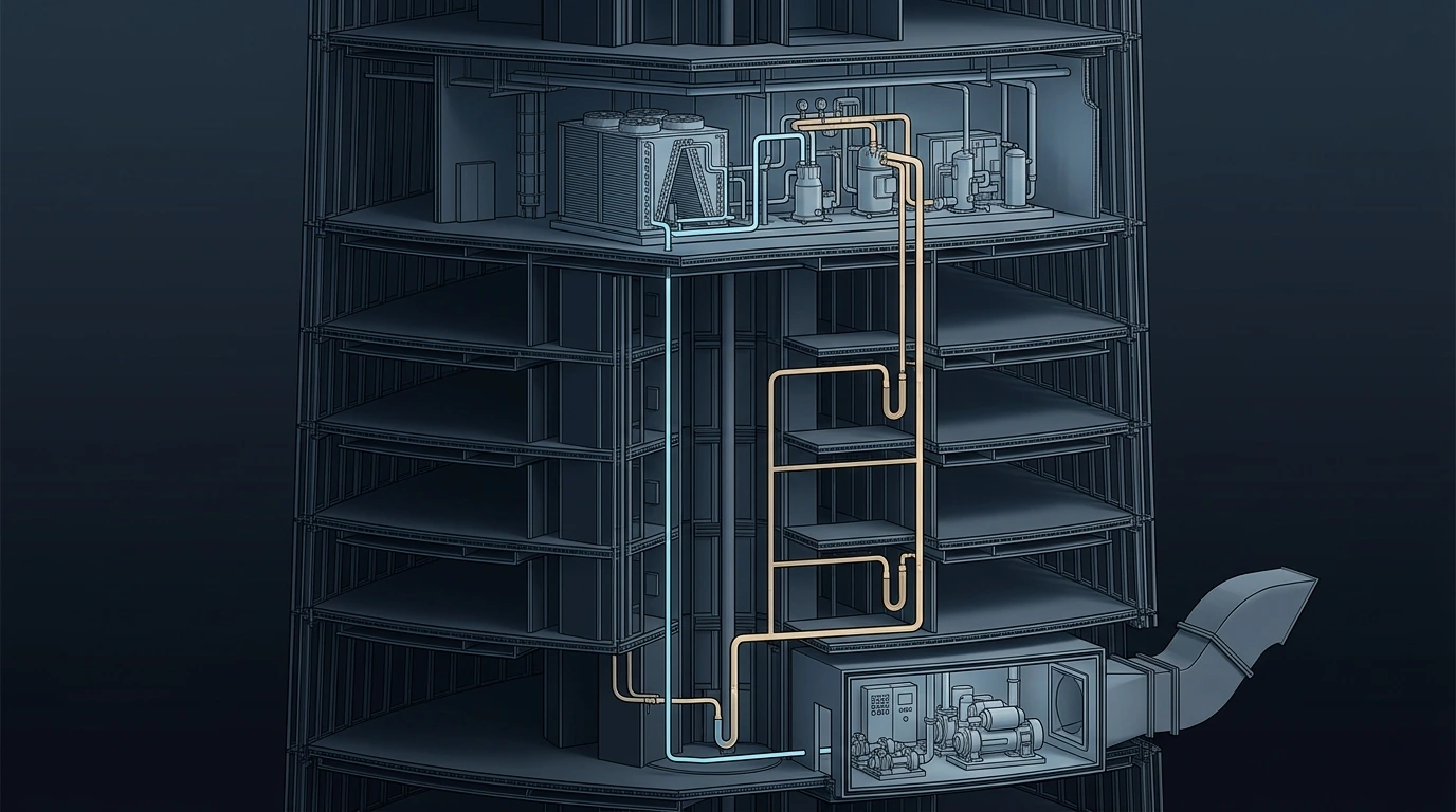
Refrigerant is the only fluid in the building that is dangerous, expensive, environmentally regulated and a gas and a liquid at the same time — and the last of those is what makes tall buildings hard. Water in a riser is just heavy. Refrigerant in a riser is a liquid column that boils if you let its pressure fall, an oil carrier that stops carrying if the velocity drops, and a charge that has to be small enough that if it all leaks into one room, the people in that room survive. Those three constraints — flash gas, oil return and refrigerant concentration limit — are what actually decide whether a direct-expansion system can be used in a tower at all, and they bite long before the capacity tables do.
1 · Three constraints, all of them vertical
- The liquid column has weight. A 100 m vertical lift in an R-410A liquid line costs about 9.3 bar of static pressure. If the liquid arrives at the expansion device below its saturation pressure it has already flashed to gas, the device loses control and the coil starves.
- Oil has to come home. Compressor oil circulates with the refrigerant and must be dragged back up vertical suction risers by gas velocity alone. Below a critical velocity it drains back, and the compressor eventually runs dry — a failure that appears months after handover and is always blamed on the compressor.
- The charge is a safety limit, not a cost item. ASHRAE 15 caps the refrigerant that may be released into an occupied space by the refrigerant concentration limit. In a tower with hundreds of small rooms, the governing room is a small one — and for the newer A2L refrigerants the allowable charge is roughly a seventh of what R-410A allowed.
2 · Static head, flash gas and the real height limit
Liquid refrigerant lifted through a height \(h\) loses static pressure \( \Delta p = \rho g h\). To arrive as liquid, it must leave the condenser sub-cooled by enough that this pressure drop does not take it below saturation:
For R-410A near 40 °C the saturation curve runs at roughly 0.60 bar/K and the liquid density is about 950 kg/m³, so every 10 m of lift consumes about 1.5 K of sub-cooling. Practical systems can deliver 10–12 K before the condenser has to be oversized or a sub-cooler added, which puts the maximum lift at roughly 77 m. That is not a manufacturer's marketing limit — it is why VRF catalogues state maximum indoor-to-outdoor height differences of 50–90 m, and it is why a tower cannot be served by one refrigerant system from a single plant deck.
3 · Interactive: sub-cooling required for a liquid lift
At the default R-410A properties, a 60 m lift costs 5.6 bar and 9.3 K of sub-cooling against 12 K available — a margin of only 2.7 K before the liquid line starts producing flash gas, and that is before line friction and a hot riser shaft are counted. The limit is about 77 m. Switch to R-134a with its shallower saturation slope and heavier liquid and the picture changes completely, which is exactly why centrifugal chillers with R-134a and a water distribution system remain the default for tall buildings while DX stays a zone-by-zone solution.
4 · Oil return — the failure that arrives eighteen months late
Oil leaves the compressor with the refrigerant and returns only if the suction gas moves fast enough to carry it up vertical risers. The minimum carrying velocity is roughly 5–7 m/s in a vertical suction riser, and — critically — it must be achieved at minimum load, not at design. A variable-capacity system that turns down to 25 % has a quarter of the velocity in a riser sized for full flow.
- Size risers on minimum load, and size horizontal runs on pressure drop. These are different criteria and they give different diameters; the riser is nearly always smaller than the horizontal main.
- Use a double suction riser where turndown is wide: a small riser sized for minimum load and a larger one that floods with oil at low load and takes over as flow rises. Fit the trap at the base and the connection at the top correctly — reversed, it does nothing.
- Trap at the base of every riser and at intervals up long risers (commonly every 6–8 m) so the oil is lifted in stages rather than as one column.
- Slope horizontal suction lines back toward the compressor so gravity helps rather than pooling oil in a low point.
- Do not oversize the pipe. Oversizing a suction line is not conservative — it is the direct cause of oil starvation. This is the opposite instinct to water design and it catches people out.
5 · Refrigerant concentration limit — the constraint that decides the system
ASHRAE 15 and ISO 5149 limit the refrigerant that may enter an occupied space so that a complete leak from the system cannot produce a hazardous concentration. The rule is simple and unforgiving[1][2]:
The governing volume is the smallest room the system serves, not the floor area or the building. In a hotel or residential tower that is a bathroom or a small bedroom, and it is brutal: a 50 m³ room permits 22 kg of R-410A, 12.5 kg of R-134a — and only 3.0 kg of R-32, because the A2L refrigerants are limited by flammability rather than toxicity. As the industry moves to lower-GWP A2L and A3 refrigerants, allowable charges fall by roughly a factor of seven, and systems that were compliant on R-410A are not on their replacement.
The design responses, in order of preference: reduce the charge (smaller circuits, more of them); increase the volume the leak can disperse into (permanent openings, ducted returns connecting spaces); detect and ventilate (leak detection with mechanical extract, which many codes accept as mitigation); or change the system to a chilled-water or DOAS arrangement where the refrigerant never leaves the plant room. In tall residential towers the last of these is increasingly the only compliant answer.
A 50 m³ bedroom permits 22 kg of R-410A, so an 18 kg circuit passes with little room to spare. Now drag the RCL down to 0.061 for R-32: the same room permits 3.0 kg and the design fails by a factor of six. That single slider is the whole refrigerant-transition problem for tall residential buildings, and it is why so many towers are moving their refrigerant into a plant room and distributing water instead.
6 · Machinery rooms, detection and emergency ventilation
Where the charge cannot be kept below the concentration limit, the refrigerant is confined to a refrigerating machinery room with its own construction, detection and ventilation requirements. ASHRAE 15 fixes the emergency ventilation rate from the largest single charge in the room[1]:
A 500 kg charge demands 1,565 L/s of emergency exhaust — about 9 air changes an hour in a 600 m³ plant room, through a 450 mm duct that must discharge somewhere safe and never near an air intake. Note the square root: doubling the charge only raises the rate by 41 %, so consolidating into fewer large machines is ventilation-efficient, while the concentration limit pushes the opposite way. Detection is the other half — sensors at low level for heavier-than-air refrigerants, alarm and ventilation interlock, a purge control outside the room, and self-closing tight-fitting doors.
7 · Installation & execution tricks
- Braze under flowing nitrogen, always. Without it the inside of the pipe oxidises and sheds scale that ends up in the expansion valves and the compressor. This is the single most-skipped and most-damaging shortcut in refrigerant pipework, and it cannot be inspected afterwards.
- Pressure-test with nitrogen, then evacuate to a target vacuum and prove it. Triple evacuation to below 500 microns with a rise test — a vacuum that climbs is either a leak or trapped moisture, and you must know which before charging.
- Weigh the charge in and record it. Charge by weight against the calculated value, and log the actual figure per circuit; regulatory leak-checking regimes are all based on the recorded charge.
- Support risers for weight and for expansion. A long copper riser moves with temperature and must be anchored and guided so the movement lands in a designed loop, not on a branch tee.
- Insulate the suction line completely, including at supports. Every uninsulated clamp on a cold suction riser inside a shaft becomes a condensation source, and in a tall shaft that water runs a long way before anyone finds it.
- Fit isolation valves and access ports per zone so a fault does not require the whole riser to be recovered — recovery of a large charge from a tall system is a multi-day operation.
- Commission at low load, not just at design. Oil return problems only appear at minimum capacity; run the system down to its lowest step and check compressor oil level and suction superheat there.
- Label the charge and the leak-check regime on the plant and in the O&M, with the responsible person named — this is a legal requirement in most jurisdictions and it is routinely missing.
8 · The design & installation checklist
- Check the concentration limit against the smallest served room, for the refrigerant actually being installed, before selecting the system type.
- Put condensing plant above the evaporators wherever possible so the liquid line falls.
- Calculate the sub-cooling budget for the lift, the friction and the shaft temperature, with margin.
- Size suction risers on minimum load, with double risers and traps where turndown is wide.
- Never oversize suction pipework.
- Plan for the A2L transition — check whether the design still complies on the replacement refrigerant.
- Design machinery rooms fully — construction, detection, emergency ventilation at 70√G, discharge location, purge control.
- Specify nitrogen purge brazing, evacuation targets and weighed charging as inspected hold points.
- Commission at minimum load and record the charge per circuit.
References & standards
- ANSI/ASHRAE Standard 15 — Safety Standard for Refrigeration Systems: occupancy classification, refrigerant concentration limits, machinery room construction, detection and emergency ventilation (Q = 70√G).
- ANSI/ASHRAE Standard 34 — Designation and Safety Classification of Refrigerants: safety groups (A1, A2L, A3, B classes) and refrigerant concentration limits; and ISO 5149 for the international equivalent.
- ASHRAE Handbook — Refrigeration, System Practices for Halocarbon Refrigerants — liquid line sub-cooling, static head, suction riser sizing, double risers and oil management.
- ASHRAE Handbook — HVAC Systems and Equipment, Variable Refrigerant Flow chapter — VRF piping limits, height differences and capacity correction.
- EN 378 — Refrigerating systems and heat pumps: safety and environmental requirements; and the EU F-Gas Regulation and equivalent national regimes on charge records and leak checking.
- ASHRAE Design Guide for Tall, Supertall, and Megatall Building Systems, 2nd ed. — refrigerant distribution and plant location in tall buildings.
- Saudi Building Code SBC 501 mechanical provisions and the Saudi regulations on refrigerant handling and machinery rooms.
- ACR/BRA and AREA industry codes of practice on brazing under nitrogen, evacuation, charging and system commissioning.