Introduction
After two decades of designing and managing water transmission networks — from 400 km+ pipeline systems in Waad Al-Shamal to 80 km transmission networks for NEOM — I've reviewed dozens of hydraulic models. One truth remains constant: the model is only as reliable as the assumptions behind it.
In this article, I share the most critical and recurring mistakes I've encountered in hydraulic modeling, with a focus on the design phase — where getting it wrong is far less costly than getting it wrong during construction or, worse, during operation.
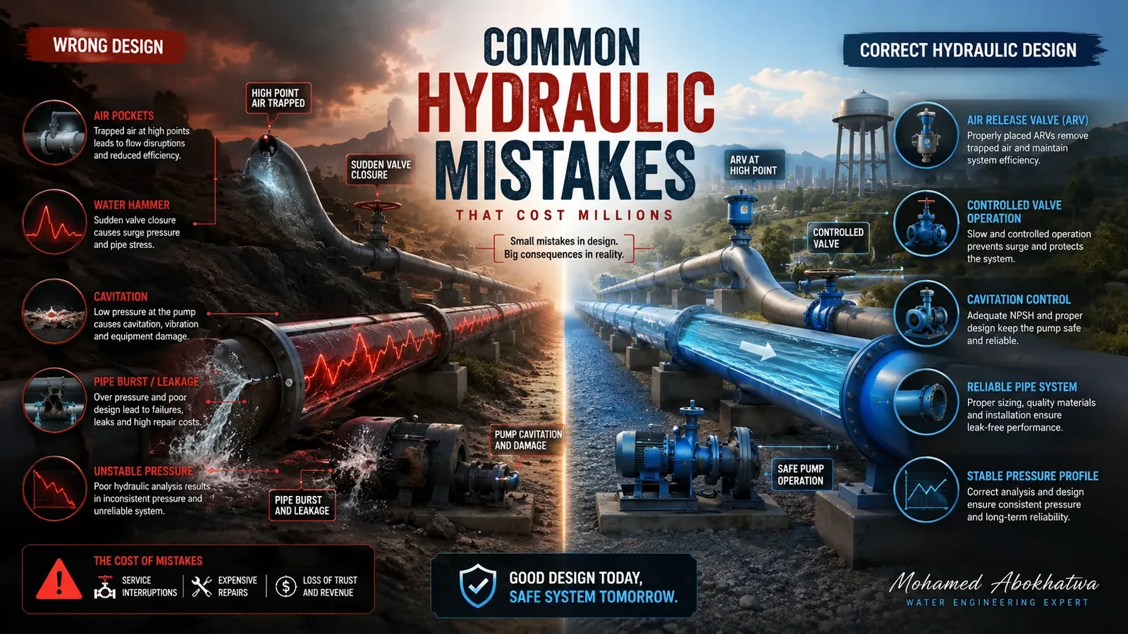
This is perhaps the most dangerous mistake of all. Many design teams model only steady-state conditions — peak demand, minimum pressure, and average flow. Steady-state tells you how the system behaves when it is stable. It tells you nothing about the critical seconds following a pump trip, valve closure, or power failure.
In a transmission pipeline designed for 145,000 m³/day at 8 bar steady-state, a sudden pump trip can generate a pressure surge exceeding 20–25 bar within 2–3 seconds — more than 3× the design operating pressure.
The pressure surge magnitude directly depends on the wave propagation speed (celerity, a), defined by the Joukowsky equation:
| Pipe Material | Wave Speed (a) |
|---|---|
| Ductile Iron (DI) | ~1,000–1,100 m/s |
| Carbon Steel (CS) | ~1,200–1,400 m/s |
| HDPE | ~200–400 m/s |
| GRP/FRP | ~400–700 m/s |
Using steel wave speed for an HDPE pipeline would overestimate surge pressure by 3–5× — leading to unnecessary over-design or false confidence in the pipe's resilience.
In real projects — especially in mountainous areas like Al-Baha or desert escarpments — elevation changes of 200–400 m over 10–30 km are common. When pressure drops below vapour pressure (~−100 kPa gauge) at a high point, column separation occurs — a vapour cavity forms, then collapses violently when pressure returns.
Air valves are a primary surge protection measure — yet their sizing and placement are frequently incorrect.
Common mistakes
4a — Placing air valves only at high points: Air valves are also needed at local high points in undulating profiles, before reducers, and upstream of long downward slopes.
4b — Undersizing the inflow orifice: For a DN 1,200 mm DI pipeline at 2.0 m/s:
- Flow rate = 1.13 m² × 2.0 m/s = ~8,140 m³/h
- Required air inflow (~22%) = ~1,800 Nm³/h — frequently underestimated
4c — Ignoring the slam effect: A combination air valve closing too rapidly generates a slam surge — sometimes more damaging than the original transient. Slow-closing or anti-slam air valves must be specified.
Specifying a surge vessel or PRV without integrating them into the transient model is a critical design gap. The right protection strategy is always determined after running the transient model — not before.
| Device | Key Parameters to Validate |
|---|---|
| Surge vessel | Volume, pre-charge pressure, connection size |
| Air/combination valve | Orifice size, placement, closing speed |
| Pressure relief valve (PRV) | Set pressure, relieving capacity, response time |
| Non-return valve (NRV) | Closing speed, disc inertia |
| Control valve | Closure time, flow characteristics |
For demand changes occurring over less than 30–60 seconds, transient analysis is required — not steady-state. Failing to recognise this boundary has led to systems that perform adequately in normal operation but fail during emergencies.
Conclusion — Design Checklist
| # | Check Item | Analysis Type |
|---|---|---|
| 1 | Steady-state pressure and velocity verified | Steady-State |
| 2 | Wave speed calculated per actual pipe material | Transient |
| 3 | Pipeline profile superimposed on HGL | Transient |
| 4 | Column separation locations identified | Transient |
| 5 | Air valve locations and sizes validated | Transient |
| 6 | Surge protection devices sized via simulation | Transient |
| 7 | Min and max pressure envelopes checked | Transient |
| 8 | Emergency / fire flow transients assessed | Transient |
| 9 | Transient report reviewed and approved | Both |
References
- Wylie, E.B. and Streeter, V.L. (1993). Fluid Transients in Systems. Prentice Hall.
- Chaudhry, M.H. (2014). Applied Hydraulic Transients, 3rd ed. Springer.
- AWWA M11 (2017). Steel Pipe — A Guide for Design and Installation.
- AWWA M51 (2017). Air-Release, Air/Vacuum, and Combination Air Valves.
- Thorley, A.R.D. (2004). Fluid Transients in Pipeline Systems, 2nd ed. Professional Engineering Publishing.
- BS EN 805 (2000). Water supply — Requirements for systems outside buildings.