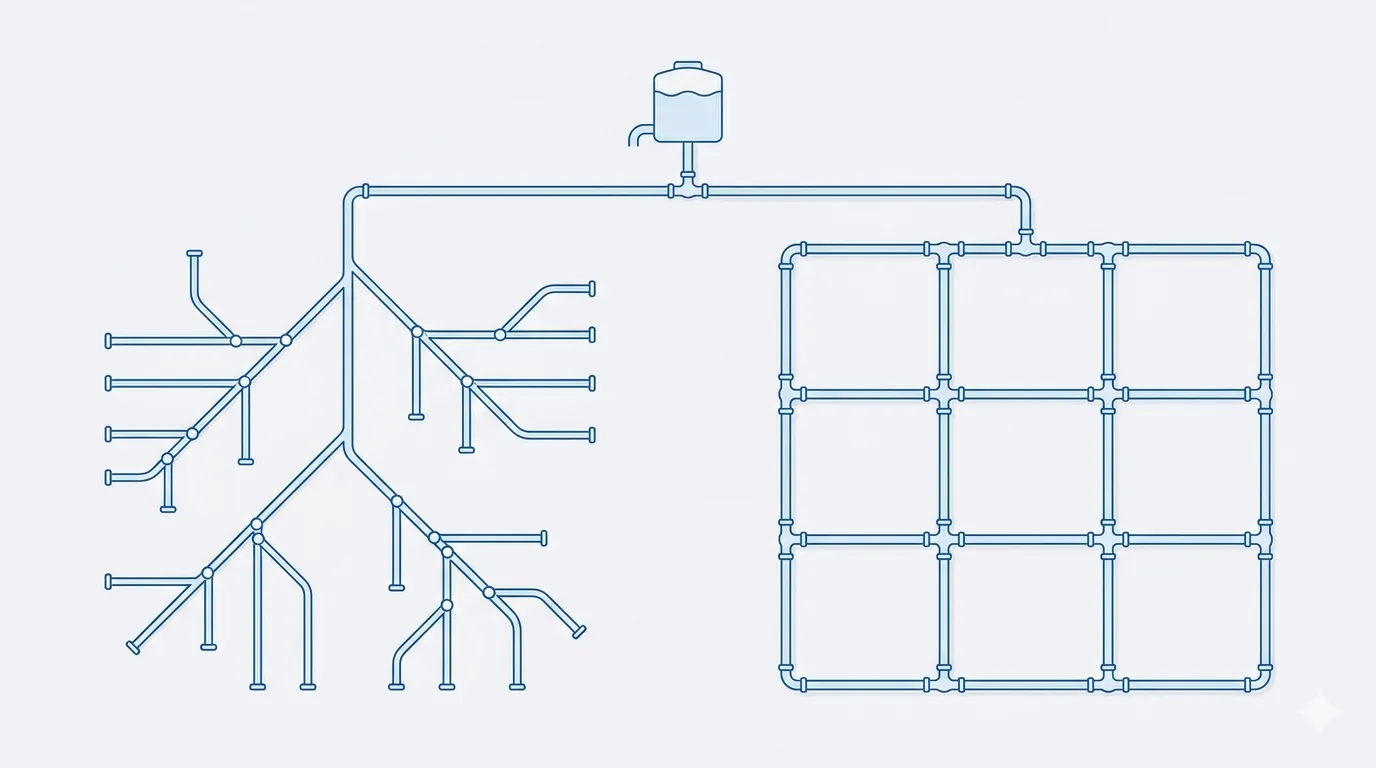
Everything upstream of the distribution network is a single decision repeated: one transmission main, one pumping station, one reservoir. The distribution network is the first time the water has to be in many places at once — and the way you connect those places, before you size a single pipe, quietly fixes four things that are expensive to fix later: the pressure at the worst house, what happens when a backhoe finds a main, whether the chlorine is still alive at the edge of town, and how much pipe you bought to get there. That decision has a name: looped or branched.
1 · The shape is the decision
Pipe sizing, valve selection and pump heads are all reversible on paper until late in design. Network topology is not. Once the corridors are committed and the pipe is in the ground, converting a branched system to a looped one means re-trenching streets that are already paved. So the looped-vs-branched choice is made first, and it sets the ceiling on everything that follows:
- Pressure — how far the head from the source actually reaches the last connection at peak demand.
- Reliability — how many customers lose water when one pipe is taken out by a break or a repair.
- Water quality — whether water moves fast enough to hold a disinfectant residual, or sits long enough to go stale.
- Cost — how much pipe length, and of what diameter, the layout demands.
2 · Branched vs looped — the two topologies
Strip a distribution network to its skeleton and there are only two ways to wire it:
- Branched (tree / dead-end). A main splits into sub-mains, which split into smaller pipes, ending in closed dead-ends. Water reaches every node by exactly one route. It mirrors how a town grows outward, uses the least pipe, and is the easiest to lay and to model by hand.
- Looped (grid / gridiron). Pipes are closed into loops so that every node is fed from two or more directions. Flow divides between the paths according to head loss, and finds its own balance — the basis of the classic Hardy Cross network analysis[5].
3 · The hydraulics: how each shares the flow
The difference is not stylistic — it changes the arithmetic of head loss. Friction in a water main follows the Hazen-Williams relation, where the loss climbs with very nearly the square of the flow it carries[9]:
That exponent of 1.852 on \(Q\) is the whole story. In a branched main, one pipe carries the entire downstream demand to the far node. In a looped main, the same far node is reached from two directions, so each leg carries only part of the flow — and because loss scales with \(Q^{1.852}\), halving the flow in a pipe cuts its head loss to about \(0.5^{1.852}\approx 0.28\) — barely a quarter. Redundancy is not only about reliability; it buys back pressure for free.
| Path to the far node | Flow per pipe | Length | Head loss |
|---|---|---|---|
| Branched — one pipe carries it all | 100 L/s | 2.0 km | 12.84 m |
| Looped — flow splits ~50/50, two legs | 50 L/s each | 1.0 km each | 1.78 m |
Same pipe, same node, same demand: 12.8 m of head lost as a dead-end versus 1.8 m through a loop — roughly a seven-fold difference, all of it pressure delivered to the customer instead of burned in friction. The first interactive chart lets you push these numbers.
4 · Interactive: pressure along the network
This is the pressure profile from the source to the far node, 2 km away, for the same demand carried two ways: a branched dead-end (one pipe, full flow) and a loop (flow split between two legs). Drop the diameter or raise the demand and watch the branched line dive through the minimum-pressure floor while the looped line holds.
At the default 100 L/s through DN300 both layouts hold pressure — but the looped node sits ~9 m higher. Drag the demand toward 200 L/s, or the diameter down to DN200, and the branched line plunges below the 14 m floor while the loop is still comfortable. The dead-end forces you to buy a bigger pipe to do what a loop does with circulation.
5 · Reliability — one break, and who keeps water
A distribution network is not designed for the day everything works; it is designed for the day a contractor's auger goes through a main, or a valve has to be closed for a new connection. This is the n−1 idea: the system should still deliver with any one element out of service[4].
Here the two topologies could not be more different. In a branched tree, every pipe is the only pipe feeding everything beyond it — so a single break or closed valve isolates the entire sub-tree downstream. Break the main near the source and the whole town goes dark. In a looped grid, closing one segment simply re-routes the water the other way around the loop; pressure dips, but supply continues. The second chart makes the contrast concrete.
6 · Interactive: the impact of a single pipe break
Take a corridor of n nodes in series. The bars show the share of customers who lose supply when one pipe segment is taken out, depending on where the break is. In the branched system the loss grows the closer the break is to the source; in the looped system, a single break isolates no one.
Slide the break toward the source: in the branched layout the cut-off share climbs to 100% — one spade through the wrong pipe and the whole line is dry. The looped layout stays flat at zero for any single failure; it takes a second, simultaneous break to isolate a node. That is the entire reliability argument for looping, in one chart.
7 · Water quality — why dead-ends go stale
The hidden cost of a dead-end is not hydraulic, it is chemical. Treated water leaves the plant with a disinfectant residual — typically free chlorine — that must survive all the way to the last tap. Chlorine decays with time spent in the pipe (its water age), following roughly first-order kinetics[7]:
In a looped network water is always in transit — flow passing through a pipe on its way somewhere else keeps the age low and the residual high. A dead-end has no through-traffic: the only water that moves is the little drawn at the end itself, so a large-diameter stub with light demand can hold water for days. As the age climbs, the residual collapses, disinfection by-products (THMs) form, and taste, odour and bacterial regrowth follow. This is why the standards actively discourage dead-end mains and, where they are unavoidable, require looping, blow-off (flushing) valves, or automatic flushers[1].
8 · Interactive: water age and chlorine at the far node
The curve is the chlorine residual decaying with water age. The two markers are the same far node served two ways: as a looped segment with through-flow (low age, left) and as a dead-end fed only by its own small demand (high age, right). Lower the demand or pick a more reactive water and watch the dead-end marker fall through the 0.2 mg/L line that most utilities hold as the minimum at the extremities.
At a healthy demand the dead-end just holds the line; throttle the demand toward 0.2 L/s — a big main with almost nothing drawn off it — and the age runs to days and the residual falls below 0.2 mg/L. The looped marker barely moves: circulation is the cheapest water-quality measure there is.
9 · Fire flow — the case looping wins outright
Domestic demand is modest and steady; the fire flow is a sudden, enormous draw at one hydrant — often several times the peak-hour demand of the whole zone, for a couple of hours, while pressure everywhere must stay above ~20 psi (14 m)[2]. A branched main has to carry that entire fire flow down a single pipe, and the \(Q^{1.852}\) law makes the head loss explode — dead-end hydrants routinely fail their flow test. A looped main delivers the same fire flow from two or more directions at once, each leg carrying a fraction, so the network holds its pressure. For any area with fire-protection requirements, looping the supply mains is effectively mandatory; AWWA's fire-protection manual is built around it[2].
10 · Cost vs. reliability — and when each one wins
None of this makes branched networks wrong. Looping costs more pipe — sometimes 20–40% more length in the supply mains — and that money has to come from somewhere. The engineering is in matching the topology to the duty:
- Loop the supply and arterial mains in any urban or suburban area, anywhere with fire flow, and around critical users (hospitals, industry). This is the backbone and it must be redundant.
- Branch the final service connections. The short pipe from a looped main to a single building is, sensibly, a dead-end — looping every house would be absurd. The art is keeping these stubs short.
- Accept branched layouts in genuinely low-density or rural extensions, at the growing edge of a network, and where a future loop is planned but not yet built — provided you manage the consequences.
- Where a dead-end is unavoidable, design the cure in from day one: a flushing/blow-off valve at the end, automatic flushers where age is critical, and a diameter no larger than the demand needs so the water still turns over.
The dominant real-world pattern is therefore a hybrid: a looped grid of supply mains carrying the reliability, water quality and fire flow, with branched service lines hanging off it. The question is rarely "looped or branched?" for the whole system — it is "what is looped, and what is allowed to dead-end?"
11 · The design checklist
- Loop the supply mains — every arterial and sub-arterial main fed from two directions; reserve dead-ends for short service stubs.
- Hold the minimum pressure — ≥ 20 psi (14 m) under all conditions including fire flow; ≥ 35 psi (25 m) desirable in normal operation[1].
- Satisfy n−1 — check that closing any single segment still serves every node above the minimum pressure.
- Deliver the fire flow — verify required flow at each hydrant from two directions while holding residual pressure[2].
- Bound the water age — keep velocities live; eliminate or flush dead-ends; avoid oversizing mains "for the future" when it lets water stagnate today.
- Check the velocities — roughly 0.6–2.0 m/s at peak; too low feeds stagnation, too high spikes head loss and surge.
- Model it — build the looped network in EPANET or an equivalent and balance the loops (Hardy Cross / gradient method) before committing pipe sizes[3].
- Plan the valving — enough isolation valves that any single break can be isolated without cutting off a large block.
References & standards
- Great Lakes–Upper Mississippi River Board (GLUMRB). Recommended Standards for Water Works (Ten States Standards) — distribution mains, minimum pressure, dead-end mains and looping requirements.
- American Water Works Association. Manual M31 — Distribution System Requirements for Fire Protection.
- American Water Works Association. Manual M32 — Computer Modeling of Water Distribution Systems.
- American Water Works Association. Manual G200 — Distribution Systems Operation and Management (reliability and n−1 practice).
- Cross, H. (1936). Analysis of Flow in Networks of Conduits or Conductors. Univ. of Illinois Engineering Experiment Station, Bulletin 286.
- Walski, T.M., Chase, D.V., Savic, D.A., et al. Advanced Water Distribution Modeling and Management. Haestad / Bentley Institute Press.
- U.S. EPA. Effects of Water Age on Distribution System Water Quality (2002); and AWWA water-quality guidance on disinfectant residuals.
- U.S. EPA. EPANET 2.2 — Hydraulic and Water Quality Modeling, user manual.
- Williams, G.S. & Hazen, A. Hydraulic Tables — the Hazen-Williams head-loss relation used throughout.