Introduction
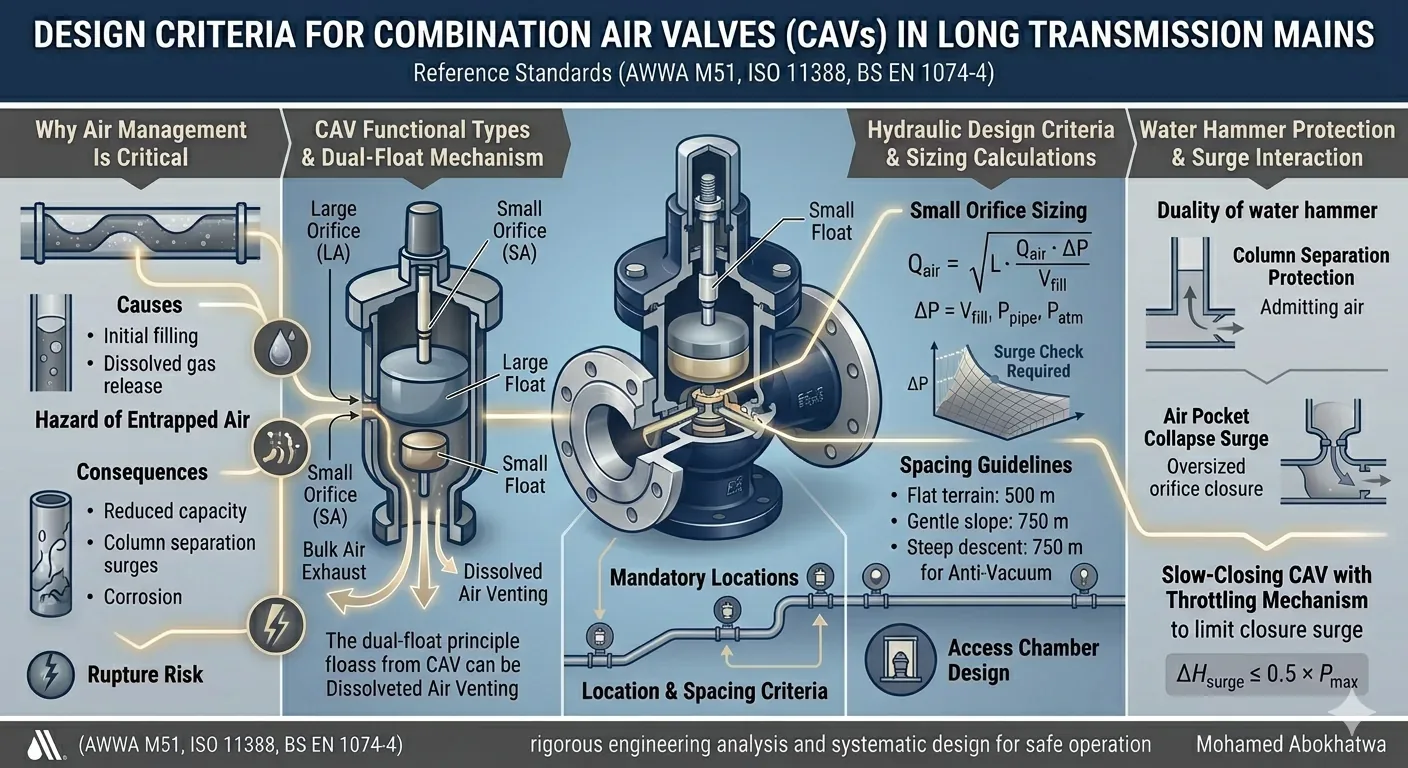
Entrapped air in pressurised transmission mains is one of the most underestimated hazards in pipeline engineering. It reduces the effective hydraulic cross-section, distorts pressure gradient lines, accelerates internal corrosion by creating oxygen-rich microenvironments, and — most critically — generates violent transient pressure surges when trapped air pockets suddenly collapse or are expelled. Documented failures trace multiple main bursts directly to unmanaged air, including a 2001 incident on a Hungarian DN 800 steel main where an entrapped air pocket at a high point triggered an overpressure of 3.2× operating pressure, rupturing the main at the flange.
Long-distance transmission mains exhibit complex longitudinal profiles with multiple high points, descending reaches, and flat plateau sections, each presenting a distinct air accumulation scenario. Addressing these systematically demands more than the rule-of-thumb approach of "fit an air valve at every high point." It requires rigorous hydraulic analysis, transient simulation, and a structured valve selection and placement methodology — aligned with AWWA M51, ISO 11388, and BS EN 1074-4.
1. Air Valve Classification
A persistent source of design errors is the conflation of the three functionally distinct air valve types. Each serves a different phase of pipeline operation, and the Combination Air Valve (CAV) exists precisely because all three scenarios occur over the lifecycle of any transmission main.
| Type | Technical Name | Operating Principle | Orifice | Application |
|---|---|---|---|---|
| Large Orifice | Air Release / Vacuum Breaker (LA) | Exhausts bulk air during filling; admits air during negative-pressure events | 10–80 mm | High points, post-pump discharge |
| Small Orifice | Continuous Air Release (SA) | Continuously vents micro-bubbles of dissolved air during steady-state operation | 1–5 mm | High points, ascending gradients |
| Combination (CAV) | CAV (LA + SA in one body) | Integrates both functions — large float for bulk air, small float for continuous venting | Two independent orifices | All critical locations on transmission mains |
| Anti-Vacuum | Vacuum Breaker (AV) | Admits air only to prevent sub-atmospheric pressure; does not exhaust air under positive pressure | Large, one-directional | Steep descending reaches |
The Dual-Float Mechanism
The CAV operates on a dual-float principle: an upper large float controls the large orifice, and a lower small float controls the small orifice. The large float remains open until rising water lifts it to seat — exhausting bulk air rapidly during filling. Once pressurised, the large float seals, while the small float continues to open and close micro-incrementally, purging dissolved air continuously.
2. Hydraulic Sizing Calculations
2.1 Large Orifice — Bulk Air Exhaust
The large orifice must exhaust the full column of trapped air during pipeline filling at the design fill rate, without generating a surge at closure. AWWA M51 §4.4 derives the governing orifice flow equation from compressible-flow orifice theory:
A = Orifice cross-sectional area (m²) | ΔP = Differential pressure (Pa) | ρair ≈ 1.225 kg/m³
For transmission mains with working pressures above 10 bar, AWWA M51 recommends limiting ΔPallowable to 0.03–0.07 bar to avoid violent closure surges. The practical sizing formula:
Vfill = Fill velocity = Qfill / Apipe (m/s) | ΔPallow = Allowable closure ΔP (bar) — typically 0.05 bar
2.2 Small Orifice — Dissolved Air Release
The small orifice is sized to continuously vent air released from solution during steady-state flow, governed by Henry's Law:
KH = Henry's constant ≈ 1.7 × 10⁻⁵ per kPa | Ppipe = Local pressure (kPa abs) | Patm = 101.3 kPa
In practice (AWWA M51 §4.3), the small orifice is sized to pass 0.5%–1.0% of the pipeline flow as air — translating to orifice diameters of 2–6 mm for most large transmission mains. Adjustable pin-type orifices are preferred over fixed-size orifices in high-turbidity applications.
3. Location Criteria Along the Alignment
The placement of CAVs is the most nuanced step in transmission main design — it sits at the intersection of topographic survey analysis, steady-state hydraulic modelling, and transient simulation. No spacing rule replaces a proper analysis of the hydraulic grade line (HGL) under multiple operating scenarios.
Mandatory Placement Locations
- Every hydraulic high point where the profile elevation change angle |θ| ≥ 0.2°
- Every upward vertical bend exceeding 5° of deflection
- Within 3–5 pipe diameters downstream of pump discharge flanges
- At every transition from ascending to steeply descending alignment
- At pipe material transitions that alter wave speed a by more than 20%
- At the downstream end of long horizontal runs exceeding 500 m in flat terrain
Spacing Criteria Between CAVs
| Terrain / Profile | Max Spacing (m) | Basis | Reference |
|---|---|---|---|
| Flat terrain (slope < 0.1%) | 500 | Limit of thermally-driven dissolved air accumulation | AWWA M51 §5.3 |
| Gentle gradient (0.1%–0.5%) | 750 | Air migrates gradually; midpoint venting required | AWWA M51 §5.3 |
| Steep gradient (> 0.5%) | 1,000 or at each crest | Air accumulates rapidly at local crests | WRc TR-30 |
| Distinct hydraulic high points | At every high point — regardless of distance | Mandatory placement — spacing override | AWWA M51 + ISO 11388 |
| Post-pump station (first segment) | Within 50 m of discharge flange | Prevent air locking in pump suction transitions | Hydraulic Institute |
| Steeply descending (> 2%) | Anti-vacuum valves every 750 m | Column separation prevention on pump-trip | ISO 11388 §6.3 |
HGL Analysis Methodology
- Plot the HGL under minimum operating flow — this is the critical condition where HGL drops closest to the profile elevation, creating the largest negative-pressure risk zones.
- Identify all profile crests above the minimum HGL — confirmed air accumulation zones requiring CAVs.
- Run a pump-trip transient simulation (AFT Impulse, Bentley HAMMER, or InfoWorks WS Pro) to identify sub-atmospheric pressure locations during the transient phase.
- Run a line-draining scenario to identify all segments requiring anti-vacuum protection.
- Classify every CAV location as: Mandatory / Probable / Precautionary.
- Apply the spacing check to flat or gently sloped segments between mandatory locations.
4. Water Hammer and CAV Surge Interaction
CAVs have a dual relationship with water hammer: they protect against negative-pressure surges by admitting air, yet they can generate positive-pressure surges if oversized or if closure occurs when an air pocket collapses. Understanding this duality is essential to rational valve sizing.
4.1 Column Separation and CAV Protection
When a pump trips suddenly, pressure drops below atmospheric — or even below vapour pressure — at high-point locations, creating a vapour cavity (Column Separation). When flow reverses and the cavity collapses, the kinetic energy of two converging water columns converts to a pressure spike known as a Column Separation Surge. A correctly sized anti-vacuum function prevents cavity formation by admitting atmospheric air before pressure drops below absolute zero gauge.
Ductile Iron: 1,100–1,300 m/s | Steel: 900–1,200 m/s | HDPE: 300–450 m/s | GRP: 700–1,000 m/s
ΔV = Sudden velocity change (m/s) | g = 9.81 m/s²
4.2 Surge from Oversized CAV Closure
If the large orifice is too large, air enters at high velocity during a pressure-drop event. When the water column returns and contacts the air pocket boundary, the pocket collapses explosively — an Air Pocket Collapse Surge. This can be 4–6× the working pressure in extreme cases (Lauchlan et al., 2005).
5. Comprehensive Worked Design Example
Design flow: Q = 1.85 m³/s (6,660 m³/h) | Max working pressure: Pmax = 16 bar (163 m w.c.)
Peak elevation: 287 m ASL at K34+200 | Fill velocity: Vfill = 3.83 m/s
1 Unconstrained large orifice at K34+200 crest
Applying the sizing formula with ΔPallow = 0.05 bar, Vfill = 3.83 m/s:
2 Surge check — maximum allowable ΔV at closure
3 Surge-constrained large orifice sizing
4 Small orifice sizing via Henry's Law
Released dissolved air at 8 bar and 28°C, distributed across 8 high-point valves on the ascending reach:
5 Placement plan by reach
| Reach | Description | Slope | Rule | CAV Locations |
|---|---|---|---|---|
| K0+000 → K15+000 | Flat terrain | 0.08% | 500 m spacing | ~30 |
| K15+000 → K34+200 | Continuous ascending | 1.2% | Every local crest | 7 |
| K34+200 → K45+000 | Steep descent | 2.4% | Anti-vacuum every 750 m | 14 |
| Post-pump stations × 2 | — | — | Within 50 m of discharge | 2 |
6. Installation Requirements
Physical Installation
- CAVs must be installed vertically upright within ±2° of plumb. Any greater deviation alters the float buoyancy geometry and shifts the closure pressure setpoint unpredictably.
- An isolation (gate) valve of the same diameter as the branch must be installed between the main and the CAV body to allow in-service maintenance without dewatering the main.
- The mounting branch must be vertical — oblique branches cause air to partially bypass the valve body and accumulate downstream of the valve.
- Minimum branch diameter = 50% of valve body diameter or DN 50 mm, whichever is greater.
- Anti-rotation brackets must be fitted on all CAVs DN ≥ 50 mm to prevent torque-induced body rotation under cyclic pressure pulsing.
- Manufacturer's minimum upstream straight pipe requirement (typically 5–10D) must be respected to avoid turbulence-induced false float actuation.
Access Chamber Design
Every CAV must be housed in a below-grade access chamber meeting the following minimum criteria: internal clear width ≥ 900 mm on the valve access side, chamber depth providing 600 mm clear space above the valve body top for removal, a removable cover with appropriate load rating, and adequate drainage to prevent chamber flooding — submerged CAVs cannot exhaust air freely.
- Extreme heat (> 45°C): aluminium protective hoods with directed ventilation apertures
- Sub-zero environments: thermal insulation and heat-trace cable; low-point drain in branch design
- High-salinity applications: 316L stainless steel wetted components; EPDM seals
- High-turbidity water (> 50 NTU continuously): dual-orifice self-cleaning small-orifice design or semi-annual cleaning
7. Common Design Errors
| # | Error | Consequence | Recommended Practice |
|---|---|---|---|
| 1 | Using the "1/10 pipe diameter" rule-of-thumb for orifice size | Consistently oversizes the large orifice — generates surge on closure | Full AWWA M51 §4 calculation with surge check at every location |
| 2 | Omitting transient analysis before specifying orifice sizes | Closure surge pressures may exceed pipe class by 2–4× | Transient simulation mandatory for any main > 5 km or P > 8 bar |
| 3 | Single CAV on a crest spanning more than 200 m horizontally | Air accumulates on both flanks; valve becomes saturated and ineffective | Two CAVs — one on each flank of the crest, 20–30 m from the apex |
| 4 | No isolation valve below the CAV | In-service maintenance requires full segment dewatering | Flanged gate valve (same DN as branch) below every CAV — mandatory |
| 5 | Neglecting steeply descending reaches (placing all valves at crests only) | No air admission path during pipe break or emergency drain — hydraulic collapse risk | Anti-vacuum valves at top of descent + every 750 m on steep descending reaches |
| 6 | Fixed small orifice in high-turbidity water | Small orifice plugs with sediment within weeks of commissioning | Self-cleaning or adjustable-pin small orifice; orifice inspection in O&M plan |
| 7 | One CAV size for the entire alignment | Over-performing at low-pressure zones; under-performing at high-pressure crests | Separate sizing calculation for each distinct location based on local HGL |
References
- American Water Works Association (AWWA) Manual M51 — Air Release, Air-Vacuum, and Combination Air Valves. 2nd Edition. Denver, CO: AWWA, 2016.
- ISO 11388:2013 — Water Supply and Wastewater Discharge Pipelines: Air Valves and Air Release Valves. ISO.
- BS EN 1074-4:2000 — Valves for Water Supply; Air Valves. British Standards Institution, London.
- Wylie, E.B. & Streeter, V.L. — Fluid Transients in Systems. Prentice Hall, 1993.
- WRc Technical Report TR-30 — Air Valve Design and Placement for Sewers and Water Mains. Water Research Centre, 2005.
- Lingireddy, S. & Wood, D.J. — "Systematic Approach to Design of Air Valve Systems." Proceedings of the ICE — Water, Maritime and Energy, vol. 148(2), 2001.
- Lauchlan, C.S. et al. — Air in Pipelines: A Literature Review. HR Wallingford Report SR 649, 2005.
- Thorley, A.R.D. — Fluid Transients in Pipeline Systems. 2nd Edition. Professional Engineering Publishing, London, 2004.
- Hydraulic Institute — Pump Application Guidelines for Pipeline Water Hammer. 3rd Edition. 2019.
- Val-Matic Valve & Mfg. Corp. — Sizing and Application Guide for Air Release and Vacuum Breaker Valves. TB-1100. 2020.