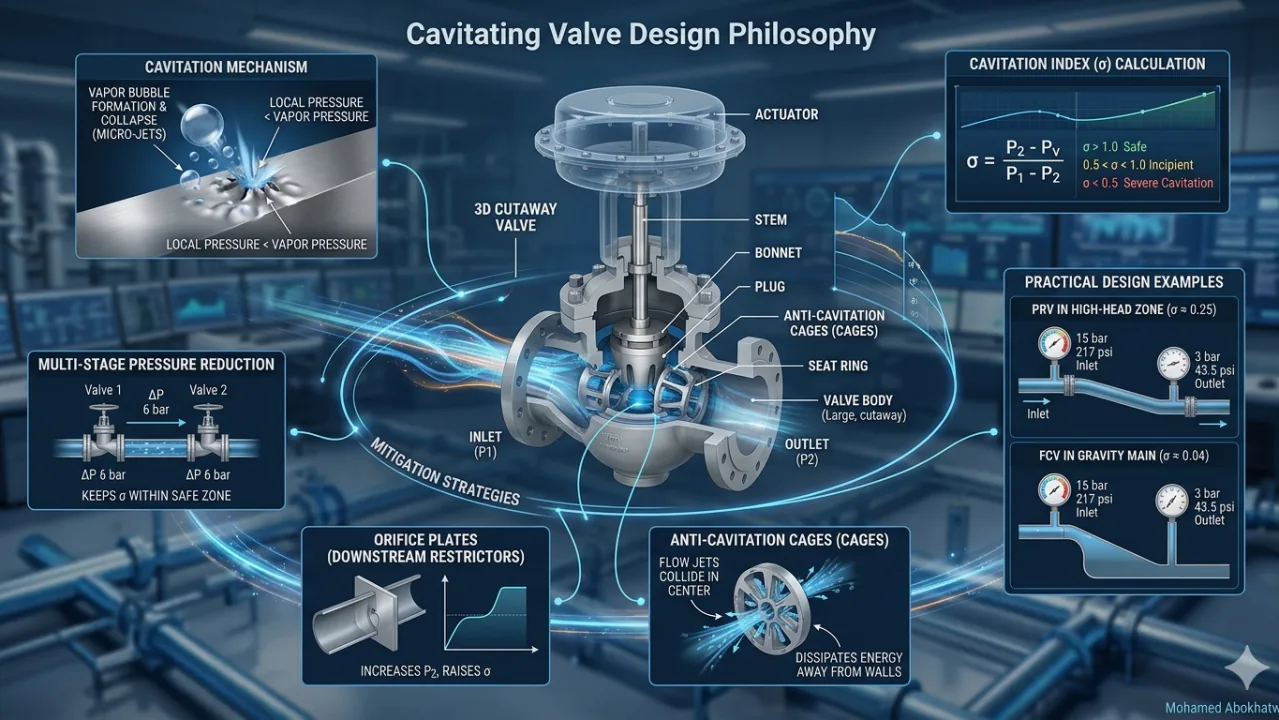
Introduction: The Physics of the "Silent Destroyer"
In water transmission networks, Pressure Reducing Valves (PRVs) and Flow Control Valves (FCVs) serve critical functions. However, when these devices operate under substantial pressure drops, local pressure within the valve trim can descend below water's vapor pressure (Pv). This creates vapor bubbles that collapse violently downstream — generating micro-jets capable of destroying valve internals within months.
1. The Cavitation Index (σ)
| σ Value | Operating Condition |
|---|---|
| σ > 1.0 | Safe operation |
| 0.5 < σ < 1.0 | Incipient cavitation (vibration and noise) |
| σ < 0.5 | Severe cavitation (immediate damage) |
2. Practical Design Example: PRV in a High-Head Zone
- Inlet Pressure (P1): 15 bar (217 psi)
- Required Outlet Pressure (P2): 3 bar (43.5 psi)
- Fluid: Water at 20°C
3. Design Example: FCV in a Gravity Line
- Upstream Pressure at Min Flow: 12 bar | Downstream Pressure (Tank head): 0.5 bar
- Pressure Drop: 11.5 bar
- Calculated σ ≈ 0.04 — cavitation is inevitable without specialized trim
4. Engineering Mitigation Strategies
A. Multi-Stage Pressure Reduction
Instead of a single valve handling the full pressure drop, deploy two valves in series, each handling half. This keeps each valve's σ within acceptable ranges.
B. Anti-Cavitation Trims (Cages)
Specialized perforated cages split flow into numerous small jets that collide in the centre of the valve, dissipating energy away from the valve walls — preventing impingement damage.
C. Orifice Plates (Downstream Restrictors)
A fixed orifice plate positioned downstream creates back pressure, increasing P2 at the valve outlet and raising the Cavitation Index to a safe operating range.
References
- AWWA M22: Sizing and Selecting Control Valves
- ISA-75.01.01: Flow Equations for Sizing Control Valves
- Cla-Val Cavitation Guide & Singer Valve Technical Calculations
- Tullis, J.P. (1989). Hydraulics of Pipelines: Pumps, Valves, Cavitation, Transients.