Introduction
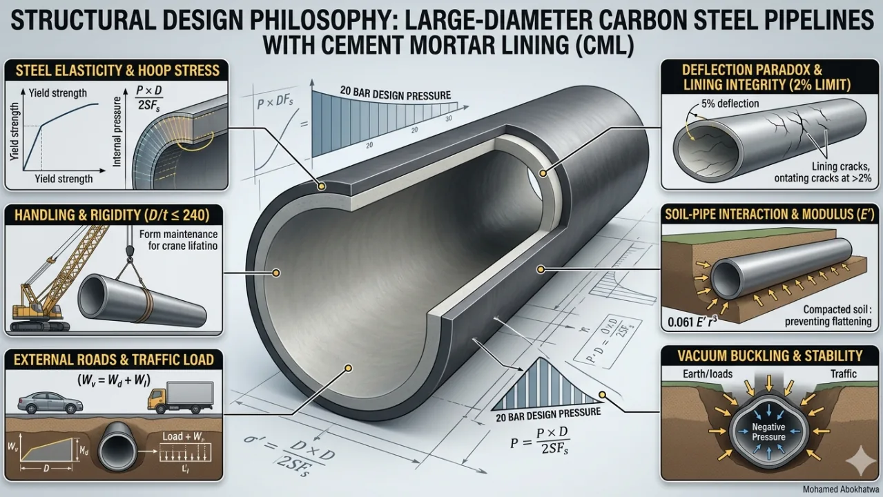
Large-diameter water transmission mains (>1000 mm) frequently employ carbon steel for its tensile strength and flexibility. When combined with Cement Mortar Lining (CML), the pipeline behavior shifts from flexible to semi-rigid. This necessitates comprehensive structural analysis beyond simple pressure calculations — balancing steel elasticity with lining brittleness while accounting for soil-pipe interaction and traffic loads.
1. Engineering Insights & Design Philosophy
The Deflection Paradox
Carbon steel can theoretically withstand 5% deflection without failing, yet CML cracks or delaminates at deflections exceeding 2%. The lining, therefore, determines serviceability limits rather than the steel itself.
Soil as a Structural Component
Buried pipes depend on soil as a structural element. The Modulus of Soil Reaction (E′) provides lateral support preventing pipe flattening — soil functions as integral to structural capacity.
Vacuum: The Silent Killer
Large-diameter pipes face greater failure risk from internal vacuum (negative pressure during surge events) than from internal burst pressure alone.
2. Detailed Design Calculation — DN 1600 mm Example
Phase I: Handling & Rigidity Check
The pipe must maintain its shape during shipping and installation.
- Rule: D/t ratio ≤ 240
- Calculation: 1600 mm / t ≤ 240
- Minimum Thickness Required: 6.67 mm
Phase II: Internal Pressure (Hoop Stress)
Based on 20 bar total design pressure (2.0 N/mm²):
Phase III: External Loading
Total load under a main highway at 3.0 m depth:
| Load Type | Value | Unit |
|---|---|---|
| Dead Load (Soil Weight) | 56.55 | kN/m² |
| Live Load (AASHTO HS-20 Traffic) | 12.0 | kN/m² |
| Total Vertical Load (Wv) | 68.55 | kN/m² |
Phase IV: Deflection Analysis (2% CML Limit)
Using the Modified Iowa Equation to preserve lining integrity:
Phase V: Buckling Stability (Negative Pressure)
Resistance against sudden internal vacuum (−1 bar):
3. Technical Summary
| Governing Factor | Required Thickness | Constraint |
|---|---|---|
| Handling | > 6.67 mm | D/t Ratio |
| Internal Pressure | > 8.94 mm | Hoop Stress |
| Lining Integrity | > 10.50 mm | 2% Deflection |
| Vacuum Stability | > 14.00 mm | Buckling |
References
- AWWA M11 (2017): Steel Pipe — A Guide for Design and Installation
- AWWA C205: Cement-Mortar Protective Lining and Coating
- AASHTO LRFD: Bridge Design Specifications (Section 12: Buried Structures)