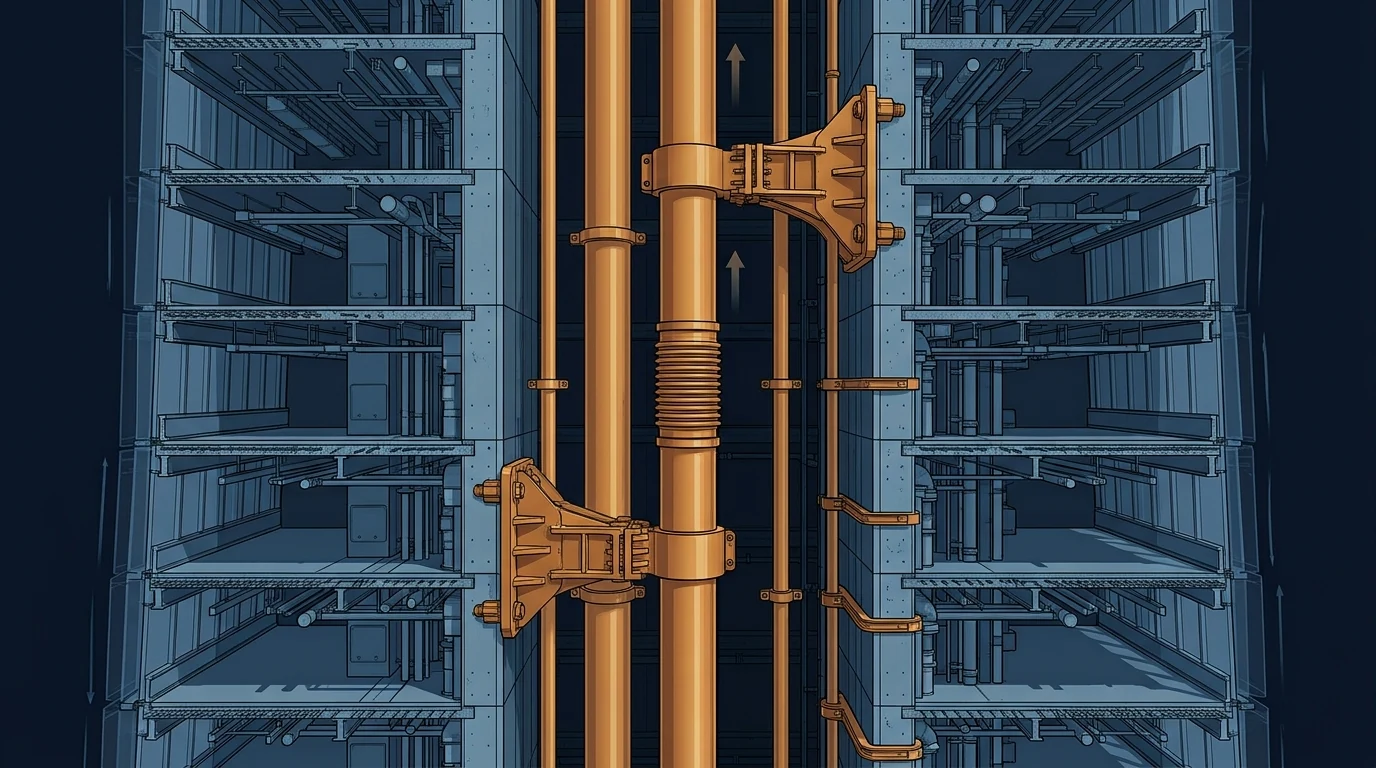
A megatall tower is not a static object. It gets shorter as the concrete creeps and dries, by hundreds of millimetres over its life. Its core and its perimeter shorten by different amounts, so the two ends of every horizontal pipe drift apart. It leans and returns in the wind, twice a minute. And the services inside it expand and contract with their own contents — a plastic riser through 30 K over 600 m moves 2.7 metres. None of this appears on a hydraulic calculation, none of it is in the pipe schedule, and all of it is capable of tearing a riser apart. Building movement is the quiet structural problem hidden inside every MEP package in a tall building.
1 · Four movements, four different timescales
- Thermal, in the service itself — minutes to hours. A chilled-water riser fills at ambient and runs at 6 °C; a hot water riser runs at 60 °C. The pipe changes length every time the system starts.
- Elastic shortening of the structure — immediate, as each floor's load is applied. Largely complete before the services are installed, but not entirely.
- Creep and shrinkage — months to decades. Concrete under sustained load keeps deforming, and it dries and shrinks. Together these dominate, and roughly a third to a half of the total happens after the pipework is fixed.
- Wind sway and differential temperature — seconds to hours, and reversible. The tower leans, and the sunlit face grows relative to the shaded one, twisting the frame slightly.
The first is the pipe moving inside a stationary building. The rest are the building moving around a pipe that would rather stay where it is. Both have to be designed for, and they are additive.
2 · Interactive: thermal movement in the riser
The classic \( \Delta L = \alpha L \Delta T\) — but in a tower \(L\) is enormous, and the coefficient depends brutally on the material you chose for reasons that had nothing to do with movement.
A 300 m steel riser through 30 K moves 108 mm overall — manageable if you break it into anchor bays so each one only has to absorb about 22 mm. Now drag the coefficient to 150 for PPR or PE-X: the same riser moves 1.35 metres, and over 600 m it is 2.7 m. Plastic pipe is chosen for corrosion resistance, weight and cost, and in a tall riser it brings a movement problem an order of magnitude larger than the steel it replaced. That is not an argument against it — it is an argument for designing the anchors, guides and compensators as part of choosing the material, rather than discovering the consequence on site.
3 · Column shortening — the movement nobody tells you about
Concrete under sustained compression keeps deforming for years, and it shrinks as it dries. The total vertical strain is the sum of three parts:
with \(\phi\) the creep coefficient, typically 1.5–2.5. For a column at 10 MPa in 35 GPa concrete with 300 µε of shrinkage, the total is around 1,150 µε — and over 600 m of building that is roughly 690 mm of vertical shortening. Structural engineers know this and compensate for most of it during construction by casting floors slightly high. What matters to the MEP engineer is the residual: the portion that occurs after the risers are installed and anchored, which is commonly a third to a half of the total — 200 to 350 mm on a 600 m tower.
On a 600 m tower the structure shortens by about 694 mm in total, of which roughly 278 mm arrives after the services are fixed — about 1.3 times the thermal movement of a 600 m steel riser through 30 K (216 mm), and in the same direction for a chilled-water system. The two are additive and they must be summed before the compensators are sized. Note the readout per zone: even broken into 40 m bays the structure still delivers 18 mm of shortening into each one, on top of the thermal swing, which is why "we have expansion joints" is not the same as "we have allowed for movement".
4 · Anchors, guides and compensators
The design method is always the same three moves, in order:
- Decide where the pipe is not allowed to move — the anchors. An anchor is a structural connection carrying real force, and it must be designed and issued to the structural engineer with a load, not drawn as a bracket.
- Force the movement into one direction — the guides. Between anchors, guides let the pipe slide axially and prevent it buckling sideways. Guide spacing comes from the buckling calculation, and the first guides either side of a compensator are much closer than the rest.
- Give the movement somewhere to go — expansion loops, offsets, or bellows/axial compensators.
Loops are preferred where space allows because they cannot fail suddenly, need no maintenance and impose only guiding forces. A guided-cantilever loop leg is roughly \( L=\sqrt{3ED\Delta/S_a}\), which for a 219 mm riser absorbing 100 mm needs an 11.5 m leg — usually impossible in a shaft, which is why tall risers use bellows.
A DN200 riser absorbing 100 mm needs an 11.5 m loop leg — which does not exist in a services shaft — so it gets a bellows, and the bellows loads its anchors with 110 kN. That is over eleven tonnes on a fixing detail that is often drawn as a channel bracket. Two design responses: use tied or pressure-balanced bellows so the thrust is carried within the assembly rather than by the building, or place the anchor at a structural element that can genuinely take it and get the load formally accepted. Either way, the number has to be calculated and issued — this is the single most under-transmitted load in MEP design.
5 · Detailing that accommodates movement
- Branches from a moving riser must be flexible. Take branches off with a swing arm or an offset long enough to flex, never with a short rigid tee straight into a fixed branch. A 20 mm riser movement against a rigid branch is a fatigue crack at the weld.
- Slab penetrations need clearance and a movement-tolerant seal. A pipe grouted solid into a slab is an unintended anchor, and it will win against the bracket you designed. Sleeve every penetration, and choose a fire-stop that is rated with movement.
- Horizontal runs from core to perimeter need articulation. This is the differential-shortening path: provide flexibility, expansion joints, or slotted supports at the perimeter end, and never fix both ends rigidly.
- Coordinate with building movement joints. Where the structure has a movement joint, every service crossing it gets a designed flexible crossing — this is elementary and it is still missed on podium-to-tower interfaces, where the movement is largest.
- Consider seismic and wind restraint together with expansion. These pull in opposite directions: restraint wants stiffness, expansion wants freedom. The answer is directional — restrain laterally, free axially — and a snubber that is set hard against the pipe defeats both.
- Insulation and cladding must move too. Rigid insulation carried through a guide, or metal cladding fixed across an expansion device, transfers force and tears. Detail the insulation at every compensator explicitly.
6 · Installation & execution tricks
- Record the installation temperature and cold-pull or pre-set every compensator to suit it. A bellows installed at neutral on a 45 °C day and then run at 6 °C spends its whole life at one end of its travel, halving its usable range and its fatigue life.
- Install anchors before the pipe is filled and verify each against the design load; an anchor added later, after the riser has already found its position, does not do what the calculation assumed.
- Check guides are actually free. Guides seized by over-tightening, by insulation packed into them or by debris are the commonest cause of a riser buckling. Inspect and record.
- Leave the travel indicators visible. Bellows and spring supports come with position indicators — do not bury them behind cladding, and photograph their as-installed positions.
- Survey the riser at intervals. Take datum readings at a few levels at handover and re-survey after twelve and thirty-six months; structural shortening is slow and a trend caught early is a cheap adjustment.
- Do not weld a temporary restraint and leave it. Temporary construction restraints on risers must be removed and their removal signed off — a forgotten one is an unintended anchor at full stiffness.
- Give the facilities team the movement drawing. Anchor and guide positions, expected travel and inspection intervals belong in the O&M; without it, a future alteration will cut the riser at an anchor.
7 · The design & installation checklist
- Sum all four movements — thermal, elastic, creep-and-shrinkage residual, and sway — before sizing anything.
- Get the post-installation shortening figure from the structural engineer, including the core-to-perimeter differential. Ask for it explicitly; it will not be offered.
- Choose pipe material with its expansion coefficient in view, especially for plastics in tall risers.
- Set anchors first, then guides, then compensators — in that order.
- Calculate and issue every anchor load, including bellows pressure thrust, to the structural engineer.
- Use tied or pressure-balanced bellows where thrust cannot be carried by the structure.
- Articulate every core-to-perimeter run and every movement-joint crossing.
- Sleeve penetrations with movement-rated fire-stopping; never grout a pipe solid.
- Pre-set compensators to the recorded install temperature and verify guides are free.
- Survey at handover and re-survey at twelve and thirty-six months.
References & standards
- ASME B31.1 Power Piping and B31.3 Process Piping — flexibility analysis, expansion stress ranges, anchor and guide design, and the guided-cantilever method.
- EJMA Standards of the Expansion Joint Manufacturers Association — bellows selection, pressure thrust, spring rates, tied and pressure-balanced arrangements.
- fib Model Code / EN 1992-1-1 (Eurocode 2) and ACI 209 — creep and shrinkage prediction models for concrete, and long-term deformation.
- CTBUH and Institution of Structural Engineers guidance on column shortening in tall buildings, differential shortening and construction compensation.
- ASHRAE Design Guide for Tall, Supertall, and Megatall Building Systems, 2nd ed. — riser support, movement accommodation and structural interface.
- CIBSE Guide B and BSRIA guidance on pipework support, anchors, guides and thermal movement in building services.
- SMACNA Seismic Restraint Manual — restraint arrangements compatible with thermal movement and directional freedom.
- Manufacturer technical data for PP-R, PE-X and PVC-U systems — expansion coefficients, support spacing and compensation detailing for plastics.