Introduction
In large-scale strategic transmission mains (DN 1000 and above), air valves are frequently treated as minor accessories — yet they are among the most critical safety components in any pipeline system. Improper sizing or placement remains a leading cause of catastrophic pipeline failure. True pipeline safety depends fundamentally on proper air management.
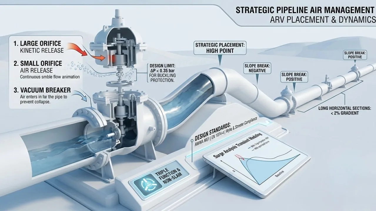
1. Strategic Placement Based on Hydraulic Profiling
Air valve locations must align with the Longitudinal Profile and Slope Breaks — not arbitrary spacing distances.
- Primary High Points: Mandatory at every peak where the HGL might drop
- Slope Breaks (Positive & Negative): Where slope changes create air accumulation potential
- Long Flat Sections: In gradients <2%, air bubbles migrate poorly — place air valves every 600–1,000 m to prevent air pockets acting as pneumatic springs
- Scour Points: Immediately downstream of isolation or scour valves
2. Sizing for Two Critical Scenarios
A. Vacuum Protection (Burst/Drainage Scenario)
This is the most critical case for large-diameter pipes. During a burst, water exits at high velocity creating a vacuum that the air valve must break:
- Air intake flow (Qair) must match potential drainage flow (Qwater)
- Internal pressure must not drop below the pipe's buckling pressure
- For large DN lines, ΔP is typically limited to 0.35 bar to prevent structural collapse
B. Controlled Air Release (Filling Scenario)
- Water filling velocity must stay below 0.3 m/s
- Air Hammer Risk: Rapid air expulsion causes trailing water to accelerate and slam into the valve seat, generating pressure spikes exceeding 50 bar — often worse than the original transient
3. Technical Features: Triple Function Combination Valves
Strategic infrastructure requires Triple Function (Combination) valves with three integrated components:
| Function | Orifice Type | Purpose |
|---|---|---|
| Rapid Air Discharge (Filling) | Large Orifice (Kinetic) | Exhaust trapped air during filling |
| Dissolved Air Release (Operation) | Small Orifice (Automatic) | Release dissolved air during pressurized flow, maintaining Hazen-Williams C factor |
| Vacuum Protection (Emergency) | Full Open (Kinetic) | Admit massive air volumes during pump trips or line breaks |
4. Professional Verdict
Air valve design constitutes a core component of Surge Analysis (Transient Modeling). Using "standard distances" without verifying HGL behavior during pump trips risks expensive forensic investigations after failure. For pipelines longer than 2 km or pump heads exceeding 30 m, air valve placement must be validated through full transient simulation — not just rules of thumb.
References
- AWWA M51: Air-Release, Air/Vacuum, and Combination Air Valves
- EN 1074-4: Performance requirements and verification tests for valves
- Wylie, E.B. & Streeter, V.L. Fluid Transients in Systems.